Stove combustor assembly

A burner and total process technology, applied in the field of cookers, can solve the problems of small combustion chamber, incomplete combustion of gas, and fire of the cooker, and achieve the effect of increasing the space of the combustion chamber, fully burning the gas, and prolonging the service life.

Inactive Publication Date: 2015-03-25
宗吉林
View PDF0 Cites 1 Cited by
  • Summary
  • Abstract
  • Description
  • Claims
  • Application Information

AI Technical Summary

Problems solved by technology

[0002] At present, the burner assembly for existing cookers in the market generally includes: ignition bracket, ignition needle, combustion chamber, induction needle, flamethrower and pot support, infrared cooker also includes porous ceramic burning plate, burner assembly inside the pot The combustion chamber is relatively small, and the gas cannot be completely burned
After a period of use, the outer ring and the inner ring of the combustion chamber will be connected to each other due to the aging and falling off of the binder due to high temperature, and the phenomenon of "blow-by" will easily occur when the gas is burned, which will cause "tempering" or "blasting" of the stove, etc. Quality issues
The ignition device is placed at the lower part of the burner assembly, resulting in an uncompact structure of the burner assembly and a relatively low gas ignition rate
The porous ceramic combustion disc is a single ring-shaped overall structure, which is prone to deformation or bursting due to thermal expansion and contraction after long-term use
The end of the infrared burner is not covered, and the infrared rays radiate to the surroundings, causing heat energy loss, reducing thermal efficiency, and causing physical discomfort to surrounding personnel due to a large amount of infrared radiation

Method used


Image

  • Stove combustor assembly
  • Stove combustor assembly
  • Stove combustor assembly

Examples


Embodiment Construction

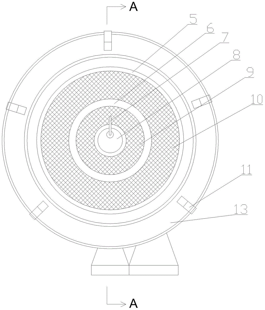
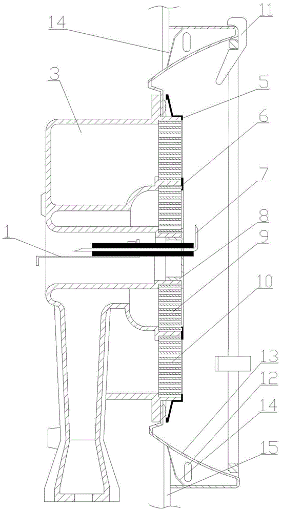
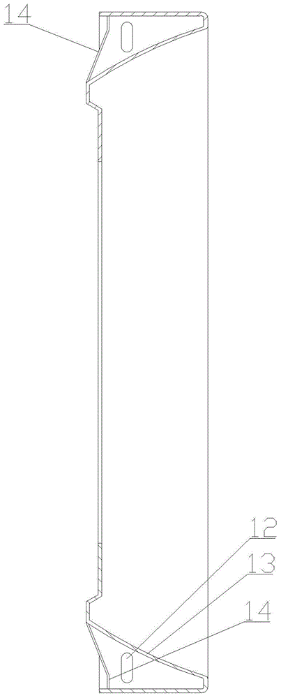
[0014] Such as figure 1 , figure 2 and image 3 As shown, the overall process of the cooker burner includes: ignition plate support 1, ignition needle, combustion chamber 3, No. Ⅰ decorative ring 5, No. Ⅱ decorative ring 6, induction needle 7, center decorative ring 8, inner ring burning plate 9, Outer ring combustion disc 10, stove frame 11, air hole 12, heat preservation disc 13, heat insulation board 14, cooker panel 15. The combustion chamber 3 of the burner is a double annular structure, and the outer ring and the inner ring are relatively isolated from the space formed by the combustion disc. The diameter range of the annular combustion chamber is 165-180 mm, and the height range of the combustion chamber is 64-90 mm.

[0015] The ignition device composed of the ignition plate bracket 1 and the ignition needle is installed at the center of the burner, so that the overall structure of the burner is more compact, and the gas ignition rate is relatively improved. The an...


PUM


Abstract

The invention relates to a stove combustor assembly, and belongs to the technical field of stoves. The stove combustor assembly comprises a combustion chamber, an ignition device, and a combustion disc and an insulation disc mounted at the ends of a combustor, wherein the combustion chamber is a double-ring structure, and an outer ring thereof is insulated from an inner ring space; the ignition device is positioned in the center position of the combustor; the combustion disc is a double-ring split porous ceramic disc; and the insulation disc is mounted at the end of the combustor. The stove combustor assembly solves the tempering problem of the stoves; the space of the combustion chamber is increased to enable the fuel combustion to become fuller; the service life of the combustion disc is prolonged; the insulation disc enables infrared rays radiated to the periphery to be reflected and concentrated to a pan bottom; and the heat efficiency of the stove combustor assembly is improved more than 30% compared with a traditional stove, so that peripheral staff cannot feel uncomfortable due to the infrared radiation.

Description

technical field [0001] The invention relates to the technical field of cooking utensils, in particular to a burner assembly for a cooking utensil. Background technique [0002] At present, the burner assembly for existing cookers in the market generally includes: ignition bracket, ignition needle, combustion chamber, induction needle, flamethrower and pot support, infrared cooker also includes porous ceramic burning plate, burner assembly inside the pot The combustion chamber is relatively small, and the gas cannot be completely burned. After a period of use, the outer ring and the inner ring of the combustion chamber will be connected to each other due to the aging and falling off of the binder due to high temperature, and the phenomenon of "blow-by" will easily occur when the gas is burned, which will cause "tempering" or "blasting" of the stove, etc. Quality issues. The ignition device is placed at the lower part of the burner assembly, resulting in an uncompact structu...

Claims


Application Information

Patent Timeline
Patent Type & Authority Applications(China)
IPC IPC(8): F23D14/14F23D14/46F23D14/82
CPCF23D14/14F23D14/46F23D14/82F23D2203/005F23D2203/102F23D2203/105F23D2209/10F23D2212/10
Inventor 宗吉林
Owner 宗吉林
Why Eureka
Try Eureka