Dryness improving device and method for improving steam dryness of steam injection boiler

A technology for steam injection boilers and lifters, which is applied to the components of steam boilers, steam boilers, steam boiler accessories, etc., can solve the problem of poor fuel atomization effect, sealing structure that does not meet sealing requirements, and unreasonable combustion chamber structure. problem, to achieve the effect of easy disassembly and replacement

Active Publication Date: 2019-11-22
北京华曦油服石油技术有限公司
View PDF13 Cites 1 Cited by
  • Summary
  • Abstract
  • Description
  • Claims
  • Application Information

AI Technical Summary

Problems solved by technology

[0003] 1. The fuel atomization effect is poor under high pressure conditions;
[0004] 2. The unreasonable structure of the fuel nozzle causes the flame backfire to cause the ablation of the nozzle, and the fuel nozzle and the nozzle are in one structure, and the ablation causes the damage of the entire nozzle, which is a serious waste;
[0006] 4. The unreasonable structure of the combustion chamber causes the flame oscillation to cause damage to the equipment;
[0007] 5. The device is characterized by high temperature and humidity saturated water vapor as the cooling medium, and the conventional sealing structure cannot meet the sealing requirements under high temperature conditions;
[0008] 6. The unreasonable heat dissipation structure of the nozzle and the combustion chamber reduces the service life of the device

Method used


Image

  • Dryness improving device and method for improving steam dryness of steam injection boiler
  • Dryness improving device and method for improving steam dryness of steam injection boiler
  • Dryness improving device and method for improving steam dryness of steam injection boiler

Examples


Embodiment 1

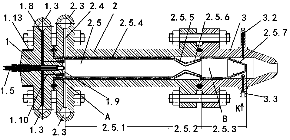
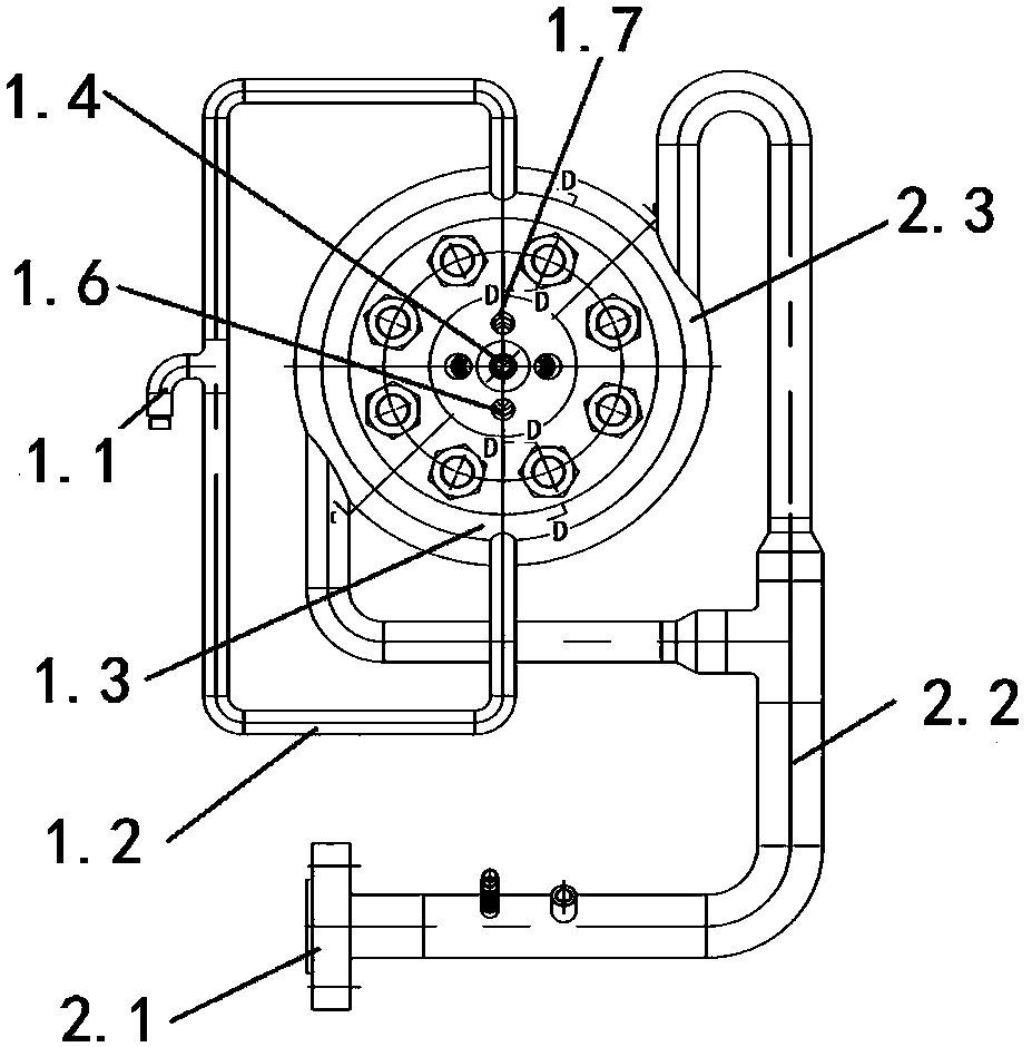
[0036] Embodiment 1, with reference to attached Figure 1-6 , a dryness lifter for improving the steam dryness of a steam injection boiler mentioned in the present invention mainly includes a front end head 1, a cylinder body 2, and a rear end head 3, wherein the front end head 1 and the cylinder body 2, the cylinder body 2 and the rear end head The ends 3 are all connected in the form of flanges.

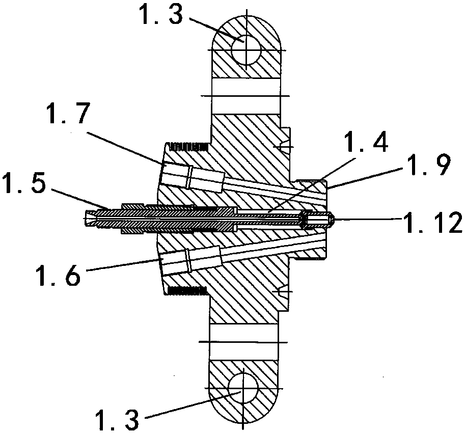
[0037] The front end head 1 is provided with a compressed air inlet 1.1, a compressed air connecting pipe 1.2, a compressed air intake passage 1.3, a fuel pipe passage 1.4, a fuel pipe 1.5, an ignition rod passage 1.6, and a flame detector passage 1.7. The compressed air intake channel 1.3, the fuel pipe channel 1.4, the ignition rod channel 1.6, and the flame detector channel 1.7 communicate with the combustion tube 2.5 respectively. The fuel pipe 1.5, the ignition rod, the flame detector and the corresponding passages are all fastened on the front end head 1 through threaded cap...


PUM


Abstract

The invention relates to a dryness improving device and method for improving steam dryness of a steam injection boiler. According to the technical scheme, a plurality of compressed air circulating holes perpendicular to a front end head are formed in a compressed air inlet channel from the middle of a flange bolt of the front end head; the compressed air inlet channel communicates with a fuel pipechannel through the compressed air circulating holes; a plurality of compressed air heat dissipating holes are formed in the front end surface of the front end head, are vertical to the compressed air circulating holes, and communicate with the compressed air circulating holes; an air heat dissipating nozzle is arranged at the tail ends of the compressed air heat dissipating holes; and a plurality of air heat dissipating spraying holes are uniformly formed in the circumference of the air heat dissipating nozzle. The dryness improving device and method have the beneficial effects that the front end head is well cooled, the compressed air is fully pre-heated in the process of cooling the front end head so as to be beneficial for atomization and combustion of fuel, and the air heat dissipating nozzle is designed on the front end surface of the front end head, so that an air cooling air film is generated on the front end surface layer of the front end head to sufficiently protect the front end surface of the front end head and various penetrating parts against high temperature damage, and the operation cost is greatly reduced.

Description

technical field [0001] The invention relates to a device and a method for increasing the steam dryness of a steam injection boiler, in particular to a dryness lifter and a method for improving the steam dryness of a steam injection boiler. Background technique [0002] At present, steam huff and puff is the main process method for thermal recovery of heavy oil, but with the increase of steam huff and puff rounds, the periodic production decline is getting bigger and bigger, and the contradictions such as formation deficit and water cut increase are becoming more and more serious. Injecting nitrogen into the oil layer, Auxiliary production increase measures such as carbon dioxide injection are becoming less and less effective as the number of rounds increases. The invention patent number applied by our unit is CN102818250B and "A Method and Device for Improving Steam Dryness of Steam Injection Boiler" was published. This process technology has made a huge breakthrough in the ...

Claims


Application Information

Patent Timeline
Patent Type & Authority Applications(China)
IPC IPC(8): F22B37/00F23D11/00F23D11/36
CPCF22B37/00F23D11/00F23D11/36F23D2214/00Y02E20/34F23D11/102F23D11/38F22B37/02F23D11/408
Inventor 薛炳平
Owner 北京华曦油服石油技术有限公司
Why Eureka
Try Eureka