Sintering machine trolley bottom two-side sealing structure

A technology of sealing structure and trolley, applied in the direction of engine sealing, mechanical equipment, engine components, etc., can solve the problems of high air leakage rate, increased air leakage rate, failure, etc., to improve the effective air volume and fan efficiency, increase production The effect of energy saving, cost reduction and solid fuel consumption reduction

Active Publication Date: 2015-03-25
PANGANG GRP PANZHIHUA STEEL & VANADIUM
View PDF7 Cites 14 Cited by
  • Summary
  • Abstract
  • Description
  • Claims
  • Application Information

AI Technical Summary

Problems solved by technology

[0003] Regarding the sealing method between the side slide plate and the slideway of the trolley, more than 90% of the sintering machines currently use a spring slide plate to compress the slideway and then add lubricating oil for sealing. However, due to the failure of the spring, the slideway, slideway Deformation, slideway oil leakage, manufacturing and installation accuracy and other reasons make the sealing effect worse or partly invalid, which significantly increases the air leakage rate
[0004] At present, there are many methods, technologies and devices to reduce the air leakage rate, such as improving the sealing material and structure, improving the lubrication method, using metal full seal, magnetic seal, etc., each has its own advantages and disadvantages, but the problem has not been fundamentally solved, and the air leakage rate remains high.

Method used


Image

  • Sintering machine trolley bottom two-side sealing structure
  • Sintering machine trolley bottom two-side sealing structure
  • Sintering machine trolley bottom two-side sealing structure

Examples


Embodiment Construction

[0017] The present invention will be further described below in conjunction with the accompanying drawings.

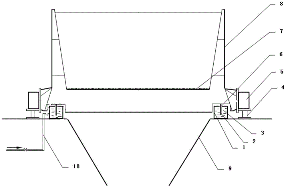
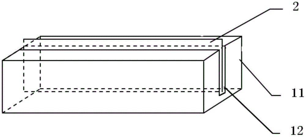
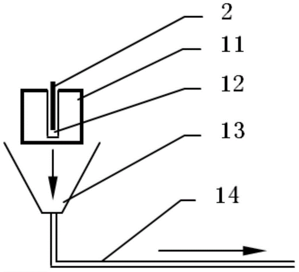
[0018] Such as figure 1 , figure 2 , image 3 The shown sealing structure on both sides of the bottom of the sintering machine trolley includes a trolley 8 and a sintering machine bellows 9 arranged under the trolley 8. The bottom of the trolley 8 on both sides is provided with a trolley wheel 5, and the trolley wheel 5 It can be slidably arranged on the trolley track 4, and also includes a pair of sealing plates 2 fixedly arranged on both sides of the bottom of the trolley 8 and extending downward in the vertical direction and a sealing water tank 1 arranged below the corresponding sealing plate 2. The sealing plate 2 is inserted into the sealing water tank 1 through the upper groove 6 of the sealing water tank to seal the bellows 9 of the sintering machine.

[0019] In view of the high air leakage rate of iron ore sintering in my country, part of the total air vo...


PUM


Abstract

The invention relates to the field of sintering machine flexible liquid sealing devices, in particular to a sintering machine trolley bottom two-side sealing structure. The sintering machine trolley bottom two-side sealing structure effectively achieves sealing of a sintering system through water seal formation. The sintering machine trolley bottom two-side sealing structure comprises a trolley and a sintering machine air box arranged below the trolley. Trolley wheels are arranged at the bottoms of the two sides of the trolley. The trolley wheels are arranged on trolley tracks in a slidable mode. The sintering machine trolley bottom two-side sealing structure further comprises sealing plates and sealing water tanks, wherein the sealing plates are fixedly arranged on the two sides of the bottom of the trolley in pairs and extend downwards in the vertical direction, and the sealing water tanks are arranged below the corresponding sealing plates. The sealing plates are inserted into the sealing water tanks through walking grooves in the upper portions of the sealing water tanks, and therefore the sintering machine air box is sealed. Due to the fact that the sealing plates are inserted into the sealing water tanks through the walking grooves in the upper portions of the sealing water tanks, the sintering machine air box is sealed relative to the exterior, the air leakage rate is lowered, and the sintering machine trolley bottom two-side sealing structure is particularly applicable to a sintering machine with the higher sealing requirement.

Description

technical field [0001] The invention relates to the field of flexible liquid sealing devices for sintering machines, in particular to a sealing structure on both sides of the bottom of a sintering machine trolley. Background technique [0002] Due to the influence of equipment structure, manufacturing installation and process conditions, etc., the iron ore ventilated sintering machine inevitably has an air leakage rate, which reduces the effective air volume of sintering, which in turn affects the quality of sintered ore and energy consumption. The air leakage rate of the domestic advanced level is about 40%, the general level is 40-60%, and the foreign advanced level reduces the air leakage rate to 20-30%. The main part of the air leakage in the sintering system is about 20% of the sealing cover plate at the head and tail of the sintering machine; about 15% of the sliding plate and slideway of the trolley; the air leakage rate of other bellows, flue, dust collector, process...

Claims


Application Information

Patent Timeline
Patent Type & Authority Applications(China)
IPC IPC(8): F27B21/08F16J15/40
Inventor 蒋大均宋剑何木光杜斯宏
Owner PANGANG GRP PANZHIHUA STEEL & VANADIUM
Why Eureka
Try Eureka