A signal generator for cable identification device

A signal generator and identification device technology, which is applied to measuring devices, parts of electrical measuring instruments, instruments, etc., can solve the problems of instruments being carried into the well ditch, signal difficulties, smoke and burnout, etc., and achieve an overall beautiful appearance, Strong anti-interference ability and guaranteed adaptability

Active Publication Date: 2017-11-07
STATE GRID CORP OF CHINA +2
View PDF6 Cites 0 Cited by
  • Summary
  • Abstract
  • Description
  • Claims
  • Application Information

AI Technical Summary

Problems solved by technology

[0006] In order to achieve safety, reliability and small size and light weight, the currently used cable identification instrument uses small and medium power for the signal generator, and the amplitude of the added current signal is affected by the grounding resistance of different cables, which often causes severe interference to the application of the signal generator by induced electricity. The pulse signal of the pulse signal, after the induction current reaches a certain value, the overvoltage protection action of the instrument will make it difficult to apply the signal. One of the reasons why the commonly used digital low-power cable identification instrument cannot work normally, which greatly affects the on-site efficiency of cable repairs and road relocation projects.
[0007] Moreover, whether it is a domestic or foreign imported instrument, the receiving instrument and the probe are relatively large, which is not suitable for the application of the test site, such as the cable well trench, where the space is small, it is difficult to move the receiving instrument, and sometimes it is even difficult to carry the instrument into the well trench; at present The laid cables are relatively tightly arranged, and the distance and space between the cables are too small to place the probe or caliper between them, which directly affects the smooth progress of the test

Method used


Image

  • A signal generator for cable identification device
  • A signal generator for cable identification device
  • A signal generator for cable identification device

Examples


Embodiment Construction

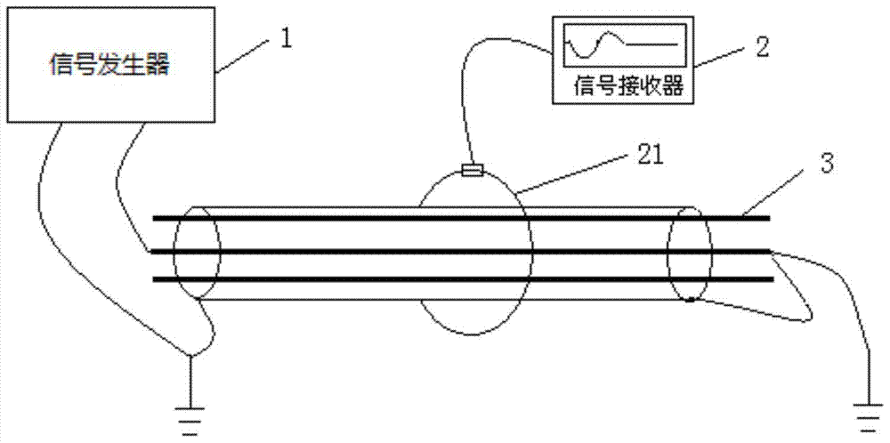
[0029] like figure 1 As shown, a cable identification device includes a signal generator 1 and a signal receiver 2. During operation, the signal generator 1 applies a high-voltage shock signal to the core of the target cable 3, and the signal propagates to the far end along the cable 3, and then It flows back to signal generator 1 through ground. At the identification point, the signal receiver 2 uses a flexible Rogowski coil 21 to measure the current signal flowing through each cable 3, and then identifies the target cable according to the characteristics of the signal.

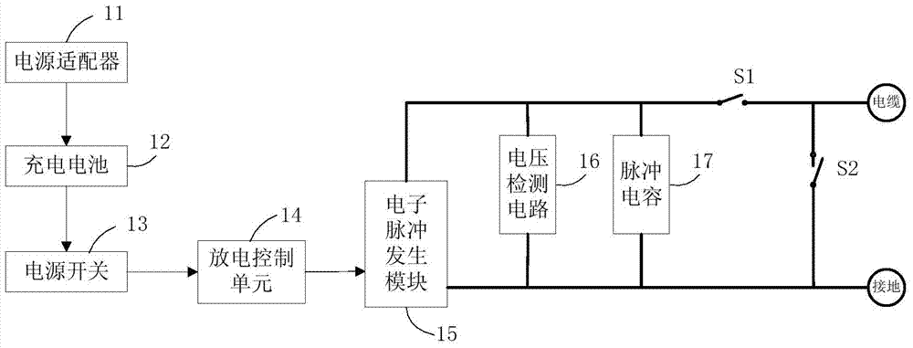
[0030] like figure 2As shown, the signal generator 1 for the cable identification device includes a power module, a high-voltage transformation unit and a discharge control unit 14, and the power module includes a power adapter 11, a rechargeable battery 12 and a power switch 13, and the power adapter will input 220VAC The power supply is converted into a 24VDC power supply to charge the rechargeable batt...


PUM


Abstract

The invention discloses a signal generator used for a cable identification device, which includes a power supply module, a high-voltage transformation unit and a discharge control unit. Circuit and pulse capacitor, the discharge control unit includes a time relay for controlling the periodic discharge of the cable, a DC electromagnet, and a mechanical periodic discharge switch connected to the output end of the pulse capacitor; the low-voltage DC power provided by the power module passes through After the discharge control unit enters the electronic pulse generation module, it directly outputs DC high voltage. The voltage detection circuit detects the output value of DC high voltage in real time. The output DC high voltage charges the pulse capacitor to provide energy for cable discharge, and then discharges the cable regularly through the discharge control unit. . The signal generator of the present invention has the characteristics of strong anti-interference, strong applicability, small volume and the like.

Description

technical field [0001] The invention relates to a signal generator used for a cable identification device, belonging to the technical field of cable identification. Background technique [0002] With the rapid development of urban economy and the improvement of the quality of life of urban residents, people have higher and higher requirements for living environment and urban appearance. Because of its safety, reliability, and advantages of beautifying the city and the layout of factories and mines, the power cable power supply has made the cable a trend in the new century and new era. It has a new practical effect on beautifying the urban environment and improving urban functions, and has been increasingly recognized. The wider the application. With the rapid development of the urban economy, the demand for electricity has also increased significantly, resulting in more and more cable repair operations and cable relocation projects. In relocation and emergency repair opera...

Claims


Application Information

Patent Timeline
Patent Type & Authority Patents(China)
IPC IPC(8): G01R1/28
Inventor 陈峰周太祥童国锋章燕卿孟永平傅成刚陈志刚
Owner STATE GRID CORP OF CHINA
Why Eureka
Try Eureka