Thin film type all-fiber current transformer with temperature compensation

A technology of current transformer and temperature compensation, applied in voltage/current isolation, measuring current/voltage, instruments, etc., can solve the problems of low measurement accuracy, achieve high measurement accuracy, eliminate errors, and simple structure

Inactive Publication Date: 2015-03-25
HARBIN UNIV OF SCI & TECH
View PDF5 Cites 11 Cited by
  • Summary
  • Abstract
  • Description
  • Claims
  • Application Information

AI Technical Summary

Problems solved by technology

[0004] The purpose of the present invention is to solve the problem that the reflective Sagnac type optical fiber current transformer is easily affected by tem

Method used


Image

  • Thin film type all-fiber current transformer with temperature compensation
  • Thin film type all-fiber current transformer with temperature compensation
  • Thin film type all-fiber current transformer with temperature compensation

Examples


specific Embodiment approach 1

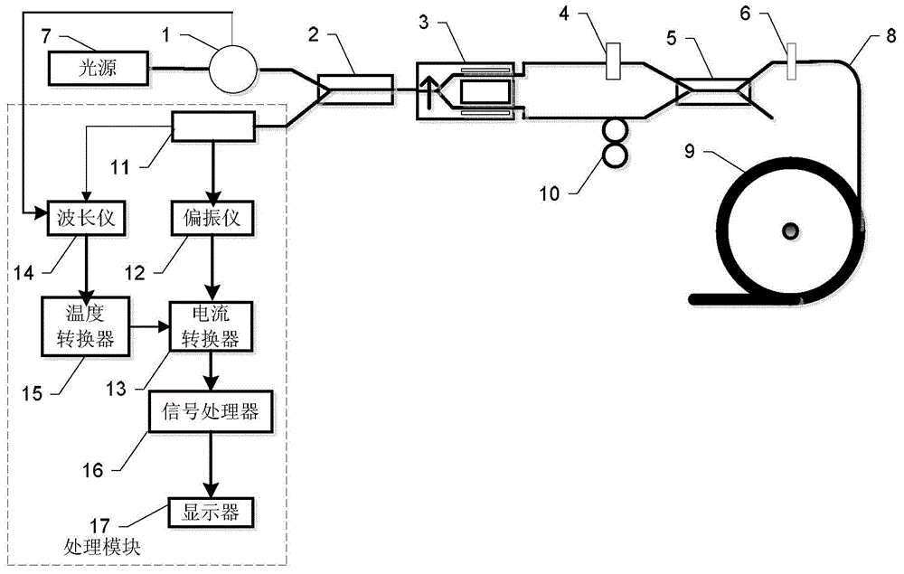
[0020] Specific implementation mode one: combine figure 1 Describe this embodiment, the thin-film all-fiber current transformer with temperature compensation described in this embodiment, the all-fiber current transformer includes a light source, an optical circulator 1, a first polarization-maintaining fiber coupler 2, and a Y waveguide Phase modulator 3, fusion branch 4, second polarization maintaining fiber coupler 5, 1 / 4 wave plate 6, transmission fiber 8, sensing fiber 9 and compensation coil 10;

[0021] The light emitted by the light source enters the first polarization-maintaining fiber coupler 2 through the circulator 1, and the light emitted by the first polarization-maintaining fiber coupler 2 enters the Y-waveguide phase modulator 3, and the Y-waveguide phase modulator 3 first converts the incident light The polarized light is converted into linearly polarized light, and then the linearly polarized light is divided into two parallel linearly polarized light outputs...

specific Embodiment approach 2

[0044] Specific implementation mode two: combination image 3 Describe this embodiment, this embodiment is a further limitation of the thin-film all-fiber-optic current transformer with temperature compensation described in the first embodiment,

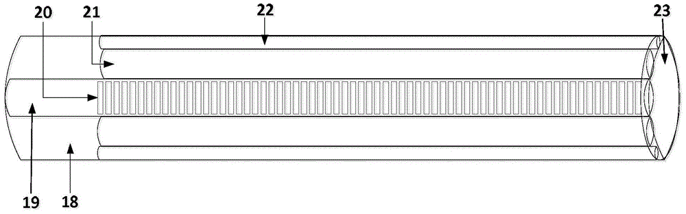
[0045] The sensing fiber 9 includes a fiber cladding 18, a fiber core 19, a FBG grating 20, a magneto-optical material 21, a reflective gold film 22 and a reflective silver film 23;

[0046] The head end of the fiber core 19 is provided with a cladding 18, and the end of the fiber core 19 is provided with a reflective silver film 23. The fiber core 19 is provided with a FBG grating 20, and the outer surface of the fiber core 19 is covered with a magneto-optical material 21. There is a reflective gold film 22 on the outer surface.

[0047] Such as image 3 Shown is a schematic diagram of the structure of the sensing fiber 9, wherein the FBG grating 20 is used for temperature measurement, the magneto-optical material 21 is used for m...

specific Embodiment approach 3

[0056] Embodiment 3: This embodiment is a further limitation of the thin-film all-fiber current transformer with temperature compensation described in Embodiment 1 or 2. The processing module includes a third polarization-maintaining fiber coupler 11, a polarimeter 12. Current converter 13, wavelength meter 14, temperature converter 15, signal processor 16 and display 17;

[0057] The light after interference in the Y-waveguide phase modulator 3 is input to the third polarization-maintaining fiber coupler 11 through the first polarization-maintaining fiber coupler 2, and the third polarization-maintaining fiber coupler 11 divides the input light into two beams,

[0058] One of them is input to the wavelength meter 14 and is compared with the light in the circulator 1 to output a wavelength shift signal, the wavelength shift signal is input to the temperature converter 15, and the temperature converter 15 outputs a temperature change signal to be input to the current converter 1...


PUM


Abstract

The invention discloses a thin film type all-fiber current transformer with temperature compensation, and belongs to the technical field of optical current sensors. The problem that a fiber current transformer is likely to be influenced by temperature and vibration, and measurement accuracy is low is solved. According to the thin film type all-fiber current transformer, light emitted by a light source passes through a circulator, a first polarization-maintaining fiber coupler and a Y-waveguide in sequence, the Y-waveguide outputs two paths of light, one path of light passes through a welding branch, rotates by 90 degrees and enters a second polarization-maintaining fiber coupler, the other path of light passes through a compensating coil and enters the second polarization-maintaining fiber coupler, the two paths of light are coupled into one path to be input into a 1/4 wave plate by the second polarization-maintaining fiber coupler, the 1/4 wave plate outputs left rotating light and right rotating light, a Faraday effect happens in a sensor fiber, and then the left rotating light and the right rotating light return to the first polarization-maintaining fiber coupler. In the return process, the original light returned through the welding branch is input into the compensating coil, the other path of light is input into a processing module through the welding branch and the first polarization-maintaining fiber coupler, and the processing module processes the input light to obtain a current value to be measured. The thin film type all-fiber current transformer is used for measuring the current value.

Description

technical field [0001] The invention belongs to the technical field of optical current sensors. Background technique [0002] Current is the basic parameter of power system, and current transformer is an important device for measuring current. For a long time, electromagnetic induction current transformers have played a very key role in current metering, power distribution, relay protection, control and monitoring in power systems. Optical current transformers have the advantages of good insulation, wide frequency band, and no magnetic saturation, and will become ideal substitutes for electromagnetic current transformers used in high-voltage and ultra-high-voltage power transmission. At present, fiber optic current transformers are the most practical type of optical current transformers, and all-fiber optic current transformers are the most promising type of fiber optic current transformers. The all-fiber optical current transformer uses low-birefringence single-mode optic...

Claims


Application Information

Patent Timeline
IPC IPC(8): G01R15/24G01R19/32
Inventor 沈涛冯月代海龙郎昌鹏邓晏豪李善强
Owner HARBIN UNIV OF SCI & TECH
Why Eureka
Try Eureka