Microwave source phase noise test method and device based on microwave photon mixing technology

A microwave photon, phase noise technology, applied in the direction of noise figure or signal-to-noise ratio measurement, can solve the problems of reduced test accuracy, working bandwidth and test accuracy limitations, etc., to achieve large bandwidth, large dynamic range, and increased operating bandwidth Effect

Active Publication Date: 2015-03-25
NANJING UNIV OF AERONAUTICS & ASTRONAUTICS
View PDF12 Cites 31 Cited by
  • Summary
  • Abstract
  • Description
  • Claims
  • Application Information

AI Technical Summary

Problems solved by technology

Due to the use of microwave mixers, microwave amplifiers and other devices, the working bandwidth and test accuracy of the above test sche

Method used


Image

  • Microwave source phase noise test method and device based on microwave photon mixing technology
  • Microwave source phase noise test method and device based on microwave photon mixing technology
  • Microwave source phase noise test method and device based on microwave photon mixing technology

Examples


Embodiment Construction

[0019] The present invention will be further described below in conjunction with the accompanying drawings.

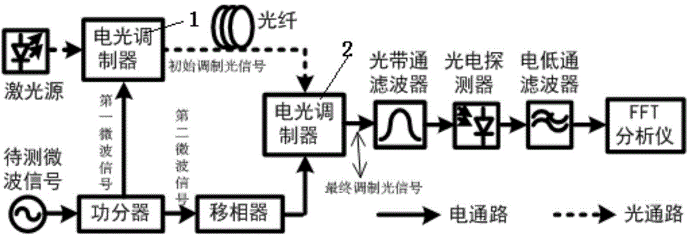
[0020] Microwave source phase noise test device based on microwave photon mixing technology, such as figure 1 As shown, it includes a microwave source, a microwave power divider, a microwave phase shifter, a laser source connected in sequence along the optical path, a first electro-optic modulator 1, an optical fiber, a second electro-optic modulator 2, an optical bandpass filter, and a photoelectric detector device, electric low-pass filter and FFT analyzer; the output end of the microwave source is connected with the input end of the microwave power splitter; the two output ends of the microwave power splitter: one of the output ends is connected with the first electro-optical modulation The drive signal input end of the device 1 is connected, and the other output end is connected with the input end of the microwave phase shifter; the output end of the microwave phas...


PUM


Abstract

The invention discloses a microwave source phase noise test method and device based on a microwave photon mixing technology. The device comprises a microwave source, a microwave power divider, a microwave phase shifter, a laser source, a first electro-optical modulator, an optical fiber, a second electro-optical modulator, an optical band pass filter, a photoelectric detector, an electric low pass filter and an FFT analyzer, wherein the laser source, the first electro-optical modulator, the optical fiber, the second electro-optical modulator, the optical band pass filter, the photoelectric detector, the electric low pass filter and the FFT analyzer are sequentially connected in the optical path direction. According to the method, a microwave signal to be tested generated by the microwave source is divided into two paths through the microwave power divider, one path of the signal is modulated through the first electro-optical modulator to generate an initial modulated optical signal, the other path of the signal enters the second electro-optical modulator after passing through the microwave phase shifter and conducts modulation on the initial modulated optical signal generated after the optical fiber is delayed, and the finally obtained modulated optical signal passes through the optical band pass filter, the photoelectric detector and the electric low pass filter sequentially; the signals output by the electric low pass filter are collected by the FFT analyzer, and the phase noise of the microwave signal to be tested is obtained through computing. The method and device have the advantages of being wide in operation bandwidth, high in test sensitivity, free of changing along with the frequency and the like.

Description

technical field [0001] The invention relates to a microwave source phase noise testing method and device based on microwave photon frequency mixing technology, and belongs to the technical fields of microwave source phase noise testing and microwave photonics. Background technique [0002] In order to meet the increasingly higher requirements for the phase noise of microwave oscillators in various military applications, researchers at home and abroad continue to reduce the phase noise of high-frequency microwave oscillators with great enthusiasm. At present, the phase noise of X-band commercial microwave oscillators is lower than -160dBc / Hz at 10kHz frequency offset (OEWaves company, 10GHz center frequency), while the general commercial phase noise analyzer can only measure -120dBc / Hz10kHz at 10GHz frequency magnitude of phase noise. In particular, the domestic measurement standard for phase noise is mainly provided by Agilent E5505A. The background phase noise at the 10GHz...

Claims


Application Information

Patent Timeline
IPC IPC(8): G01R29/26
Inventor 张方正朱登建潘时龙周沛
Owner NANJING UNIV OF AERONAUTICS & ASTRONAUTICS
Why Eureka
Try Eureka