
Input-matching standing-wave ratio adjusting circuit for low-noise amplifier

A low-noise amplifier, input matching technology, applied in the direction of improving amplifiers to reduce noise effects, negative feedback circuit layout, etc., can solve problems such as standing wave ratio not meeting specifications, and achieve the effect of convenient production and debugging

Inactive Publication Date: 2015-03-25
JIALV COMM EQUIP SHANGHAI
View PDF0 Cites 5 Cited by
  • Summary
  • Abstract
  • Description
  • Claims
  • Application Information

AI Technical Summary

Problems solved by technology

[0010] (3) The traditional matching circuit of the low-noise amplifier uses ordinary high-frequency inductance and capacitance for matching. Due to the difference in incoming materials, the standing wave ratio does not meet the specifications.

Method used


Image

  • Input-matching standing-wave ratio adjusting circuit for low-noise amplifier
  • Input-matching standing-wave ratio adjusting circuit for low-noise amplifier
  • Input-matching standing-wave ratio adjusting circuit for low-noise amplifier

Examples


Embodiment Construction

[0024] The present invention will be further described below in conjunction with the accompanying drawings.

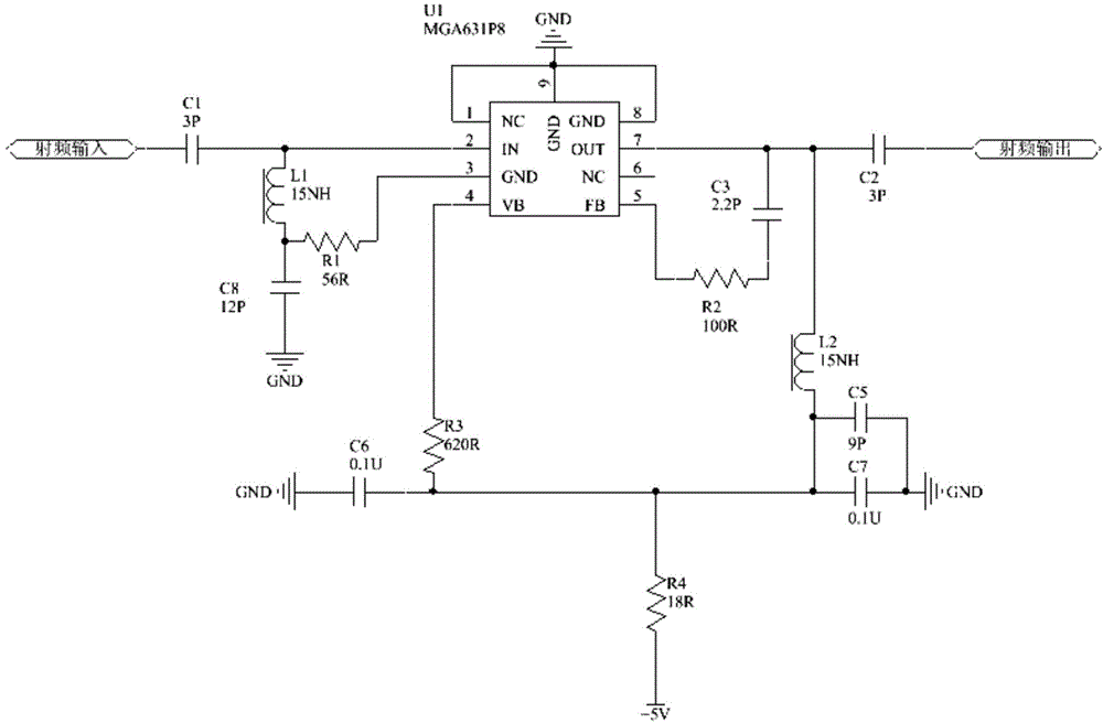
[0025] Such as figure 1 As shown, the working voltage of the low noise amplifier MGA631P8 is 4V, 54mA, the power supply is +5V, the current limiting resistors R3 and R4 are required, C6 and C7 are decoupling capacitors, and C5 is a bypass capacitor. The input matching circuit is composed of capacitors C1, C8, and inductor L1, and the characteristic impedance of the input circuit is controlled by adjusting the value of the capacitor and inductance. The matching circuit at the output end is composed of a capacitor C2 and an inductor L2, and the resistor R2 and capacitor C3 form a feedback. By adjusting the resistance value of R2, the gain of the low noise amplifier is adjusted to achieve an appropriate gain.

[0026] The low-noise amplifier input matching standing wave ratio adjustment circuit of the present invention comprises a low-noise amplifier, an input-end matchi...


PUM


Abstract

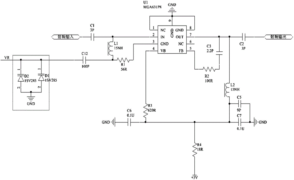
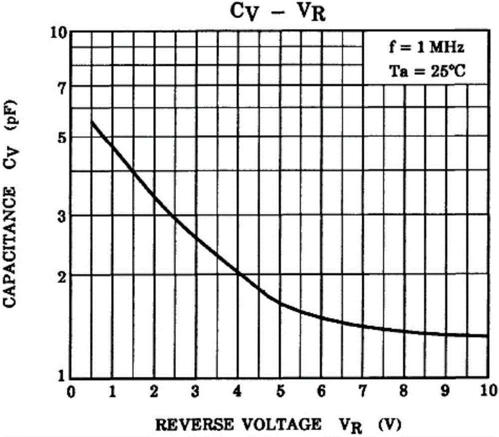
The invention relates to an input-matching standing-wave ratio adjusting circuit for a low-noise amplifier and provides a circuit allowing the standing-wave ratio of the low-noise amplifier to be effectively adjusted. The input-matching standing-wave ratio adjusting circuit comprises two variable capacitance diodes; anodes of the variable capacitance diodes are grounded, and cathodes of the variable capacitance diode are connected with ground pins of the low-noise amplifier; reverse bias voltage is input to the reverse ends of the variable capacitance diodes; junction capacitances of the variable capacitance diodes change with adjustment of the reverse bias voltage; thus, characteristic impedance of the input end of the low-noise amplifier is changed, and the standing-wave ratio is adjusted. The input-matching standing-wave ratio adjusting circuit is applicable to the adjustment of the standing-wave ratio in GSM (global system for mobile communications), CDMA (code division multiple access), GPS (global positioning system) and ISM (industrial scientific medical) bands.

Description

technical field [0001] The invention relates to a low-noise amplifier input terminal standing wave ratio adjustment circuit, which is especially suitable for debugging production of the low-noise amplifier input terminal standing wave ratio in mobile communication repeaters and base stations. Background technique [0002] Standing wave ratio full name voltage standing wave ratio, English is VSWR (Voltage Standing Wave Ratio), in the place where the incident wave and the reflected wave have the same phase, the voltage amplitude is added to the maximum voltage amplitude Vmax, forming an antinode; in the incident wave and reflected wave Where the phases are opposite, the voltage amplitudes are subtracted to the minimum voltage amplitude Vmin, forming a node. The amplitude values ​​of other points are between antinodes and nodes. This synthetic wave is called a standing wave. The standing wave ratio is the ratio of the voltage amplitude Vmax at the antinode of the standing wav...

Claims


Application Information

Patent Timeline
IPC IPC(8): H03F1/26H03F1/34
Inventor 许汉铭
Owner JIALV COMM EQUIP SHANGHAI
Learn More