
Differential charge amplifier with high precision, low temperature drift and low offset

A charge amplifier, high-precision technology, used in differential amplifiers, charge amplifiers, amplifiers, etc., can solve the problems of large feedback resistance, large temperature drift and offset voltage of the charge amplifier, and interference, and achieve small temperature drift and high amplification accuracy. , the effect of small bias voltage

Inactive Publication Date: 2015-03-25
AVIC NO 631 RES INST
View PDF7 Cites 3 Cited by
  • Summary
  • Abstract
  • Description
  • Claims
  • Application Information

AI Technical Summary

Problems solved by technology

Traditional charge amplifiers generally use single-ended amplification (such as Image 6 Shown), and then filtered measurement method, this measurement method is susceptible to common-mode signal interference, and because in order to meet the requirements of the measurement frequency range and accuracy, the selected feedback resistor is relatively large, making the temperature drift of the charge amplifier and offset voltage are large, affecting the measurement accuracy of the entire amplifier
Traditional differential amplifier circuits (such as Figure 7 Shown) only overcomes the interference problem of the common mode signal, but cannot solve the problem of temperature drift and offset voltage of the amplifier

Method used


Image

  • Differential charge amplifier with high precision, low temperature drift and low offset
  • Differential charge amplifier with high precision, low temperature drift and low offset
  • Differential charge amplifier with high precision, low temperature drift and low offset

Examples


Embodiment Construction

[0033] Below in conjunction with accompanying drawing and embodiment the present invention will be further described:

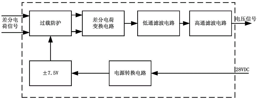
[0034] Such as figure 1 As shown, the differential high-precision low-temperature drift low-offset charge amplifier of the present invention includes an overload protection circuit, a differential charge conversion circuit, a low-pass filter circuit, a high-pass filter circuit and a power conversion circuit. The power conversion circuit provides appropriate power to other circuits.

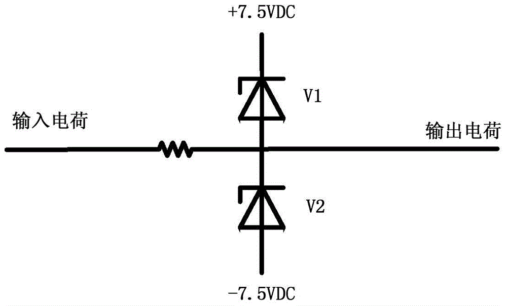
[0035] The overload protection circuit consists of protective transient suppression connected in series, such as figure 2 As shown, it is used to limit the impact of excessive charge on the subsequent circuit.

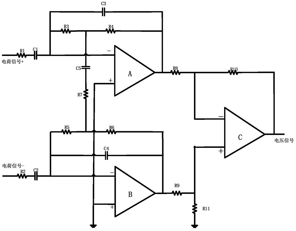
[0036] The differential charge conversion circuit is connected with the overload protection circuit, receives the charge signal passed through the overload protection circuit, and transforms it into a voltage signal after being differentially amplified. Such as ima...


PUM


Abstract

The invention provides a differential charge amplifier with high precision, low temperature drift and low offset, the differential charge amplifier has the advantages of high amplification precision on charge signals, small temperature drift and low offset voltage, and can be used for accurately amplifying vibration charge signals. The amplifier structurally comprises an overload protection circuit, a differential charge conversion circuit, a low-pass filter circuit and a high-pass filter circuit, which are connected in sequence, and a power supply conversion circuit used for supplying power to the circuits, wherein the differential charge conversion circuit comprises a first inverting amplifying circuit, a second inverting amplifying circuit and a subtraction operation circuit; a Qp anode and a cathode of a charge signal are respectively connected to the first inverting amplifying circuit and the second inverting amplifying circuit through capacitors, and the feedback resistance branches of the two inverting amplifying circuits respectively form T-shaped networks with the same RC series branch; the outputs of the first inverting amplifying circuit and the second inverting amplifying circuit serving as a positive phase input and a negative phase input are respectively connected to the subtraction operation circuit.

Description

technical field [0001] The invention belongs to the technical field of vibration monitoring, and specifically relates to a mechanical shock and vibration signal amplification processing circuit, which is used for the amplification and processing of charge signals under various shock and vibration environments. Background technique [0002] At present, the measurement and control technology of non-electrical physical quantities involves a large number of vibration signals. In real life, the magnitude of vibration signals is often measured by acceleration, which is generally measured by piezoelectric acceleration sensors. The output of the piezoelectric acceleration sensor needs to be transformed by the charge amplifier (that is, the charge-voltage conversion) before it can be used for subsequent amplification and processing. Therefore, the charge amplifier is an indispensable secondary instrument in acceleration measurement, and a charge amplifier with good performance should ...

Claims


Application Information

Patent Timeline
IPC IPC(8): H03F3/70H03F3/45H03F1/30
CPCH03F1/30H03F3/45973H03F3/70H03F2203/45138
Inventor 赵建平赵小勇刘骁喻鸣郝建
Owner AVIC NO 631 RES INST
Learn More