
Numerical control milling machine realizing moving of gantry under driving of gear and rack

A technology of rack and pinion, CNC milling machine, applied in milling machine equipment, milling machine equipment details, large fixed members and other directions, can solve the problems of limiting CNC milling machine, labor and time, cost increase, etc. Time saving effect

Active Publication Date: 2015-04-01
宁波市凯博数控机械有限公司
View PDF7 Cites 9 Cited by
  • Summary
  • Abstract
  • Description
  • Claims
  • Application Information

AI Technical Summary

Problems solved by technology

[0002] The CNC milling machine uses a servo motor to drive the X, Y, and Z slides through the ball screw pair to realize three-dimensional milling. The ball screw pair is a rotating mechanism that converts rotary motion into linear motion. Due to the limitation of material elasticity , the ball screw pair should not be too long, thus limiting the length of the Y-direction working stroke of the CNC milling machine
Workpieces that need to be processed longer than the length of the Y-direction working stroke of the CNC milling machine are called super-long workpieces; for super-long workpieces, the existing technology adopts the method of segmented U-turn processing, that is, a certain side section of the super-long workpiece is processed first, and then U-turn Processing the other side section of the ultra-long workpiece; in this way, it is labor-intensive and time-consuming to find the correct position of the turning and clamping, the efficiency is low, the cost is increased, and the defect of the processing seam will be left; therefore, the existing technology is labor-intensive, time-consuming, inefficient, Problems and deficiencies of high cost and process seam defects

Method used


Image

  • Numerical control milling machine realizing moving of gantry under driving of gear and rack
  • Numerical control milling machine realizing moving of gantry under driving of gear and rack
  • Numerical control milling machine realizing moving of gantry under driving of gear and rack

Examples


Embodiment Construction

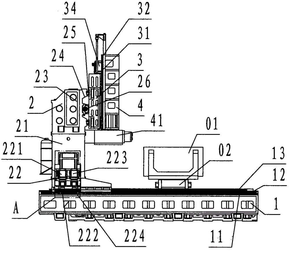
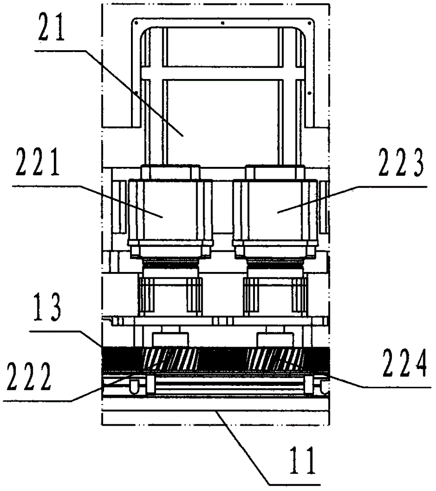
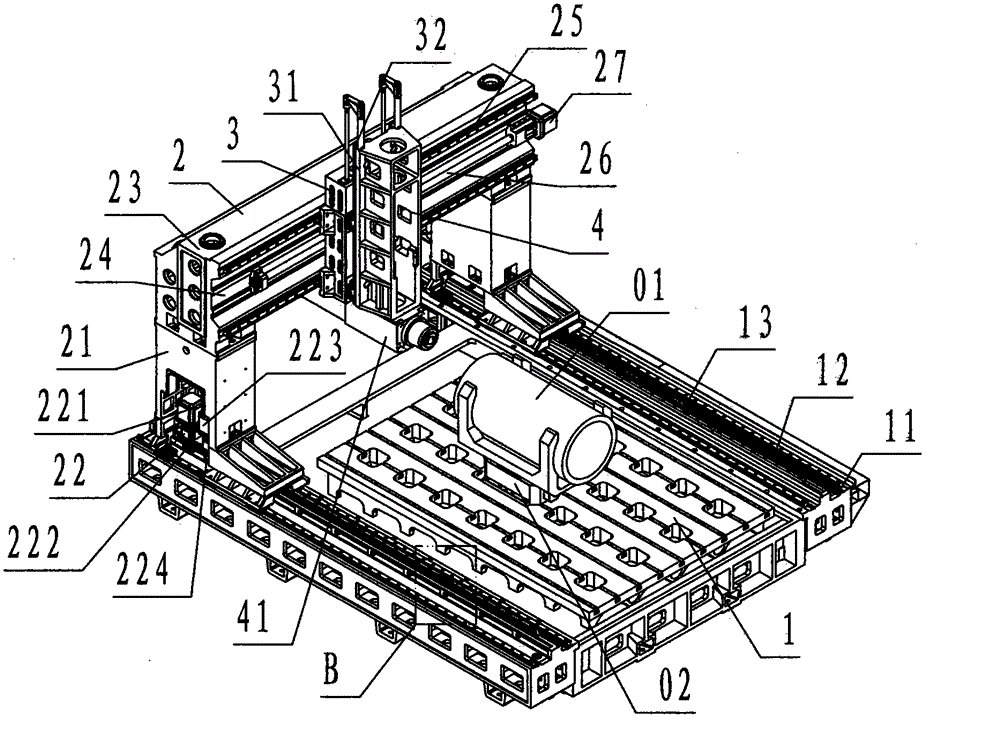
[0025] refer to Figure 1 to Figure 6 , a kind of numerically controlled milling machine that drives the gantry to move by rack and pinion of the present invention, comprises fixed worktable 1, Y movable gantry 2, orthogonal carriage 3, Z carriage 4, wherein: described fixed workbench 1 is top view It is a rectangular cast iron component, and the front and rear sides of the fixed workbench 1 are respectively provided with a rectangular platform in the left and right direction, which is called the Y rail base 11. On the Y rail base 11, there are two rollers parallel to each other and in the left and right directions. The guide rail pair is called the Y rail pair 12, and the helical racks protruding upward and left and right are arranged between the two Y rail pairs 12 and are called racks 13; The teeth face forward, and the teeth of the rack 13 positioned at the rear of the fixed workbench 1 face backward;

[0026]The Y moving gantry 2 is a door frame-shaped cast iron componen...


PUM


Abstract

The invention discloses a numerical control milling machine realizing moving of a gantry under driving of a gear and a rack. The numerical control milling machine comprises a fixed table (1), a Y movement gantry (2), an orthogonal carriage (3) and a Z carriage (4). According to the invention, Y rail bases are arranged on two sides of the fixed table, the Y movement gantry is connected with a Y rail pair to be capable of moving on the Y rail bases left and right, and is driven through meshing of a double-wheel driving device and the rack. During working, a workpiece is clamped on the fixed table, the Y movement gantry does Y-direction movement left and right, the orthogonal carriage does X-direction movement front and back, and the Z carriage does Z-direction movement up and down, so as to guide a cutting tool mounted on an electric spindle to carry out three-dimensional cutting processing on the workpiece together; according to the technical scheme, the gapless meshing between the double-wheel driving device and the rack drives the Y movement gantry, the length of the rack is not limited, and the Y-direction work stroke design length of the machine tool can be randomly extended, so that numerical control milling of an ultralong workpiece is time-saving, efficient, low in cost, and free of technological seam defects.

Description

technical field [0001] The invention relates to a numerically controlled milling machine, in particular to a numerically controlled milling machine which is used for three-dimensional automatic milling and processing of ultra-long workpieces, which is driven by a rack and pinion to move a gantry. Background technique [0002] The CNC milling machine uses a servo motor to drive the X, Y, and Z slides through the ball screw pair to realize three-dimensional milling. The ball screw pair is a rotating mechanism that converts rotary motion into linear motion. Due to the limitation of material elasticity , The ball screw pair should not be too long, thus limiting the length of the Y-direction working stroke of the CNC milling machine. Workpieces that need to be processed longer than the length of the Y-direction working stroke of the CNC milling machine are called super-long workpieces; for super-long workpieces, the existing technology adopts the method of segmented U-turn proces...

Claims


Application Information

Patent Timeline
IPC IPC(8): B23C3/00B23Q5/40B23Q5/34B23Q1/25B23B21/00
CPCB23C3/00B23Q1/626B23Q5/40
Inventor 俞湘左黔湘沈良永黄吉能叶显巧储善谦
Owner 宁波市凯博数控机械有限公司
Learn More