FPGA-based (Field Programmable Gate Array-based) IO (Input/Output) bus device with automatic recognition function

A bus device and self-identification technology, applied in the bus field, can solve problems such as unreliable connection between boards and backplanes, inability to plug in other types of boards, wrongly plugging in wrong power boards, etc., to save query or interruption time, Easy to program processing, easy to update the effect

Active Publication Date: 2015-04-01
NANJING INTELLIGENT APP
View PDF4 Cites 20 Cited by
  • Summary
  • Abstract
  • Description
  • Claims
  • Application Information

AI Technical Summary

Problems solved by technology

First of all, this transmission method fixes the position of each board, that is, each board can only be inserted into the fixed position of the backplane, and the connection between the backplane and the main CPU board has been fixed at the beginning of the design. The slots on the board cannot be inserted into other types of boards
Secondly, wrongly inserting boards may cause damage to the device, especially wrongly inserting the wrong power board or analog board may cause damage to the main CPU board
Third, due to the large number of dedicated connections and the lack of intelligent self-checking and identification functions in the protection device, oxidation of the board connectors will occur during long-term work, resulting in unreliable connection between the board and the backplane, and input signals cannot be is correctly identified, the output signal may also act incorrectly
Fourth, with the increasing demand for protection devices in power equipment, the CPU needs to be updated frequently, and traditional devices often require substantial modification of hardware and programs

Method used


Image

  • FPGA-based (Field Programmable Gate Array-based) IO (Input/Output) bus device with automatic recognition function
  • FPGA-based (Field Programmable Gate Array-based) IO (Input/Output) bus device with automatic recognition function
  • FPGA-based (Field Programmable Gate Array-based) IO (Input/Output) bus device with automatic recognition function

Examples


Embodiment Construction

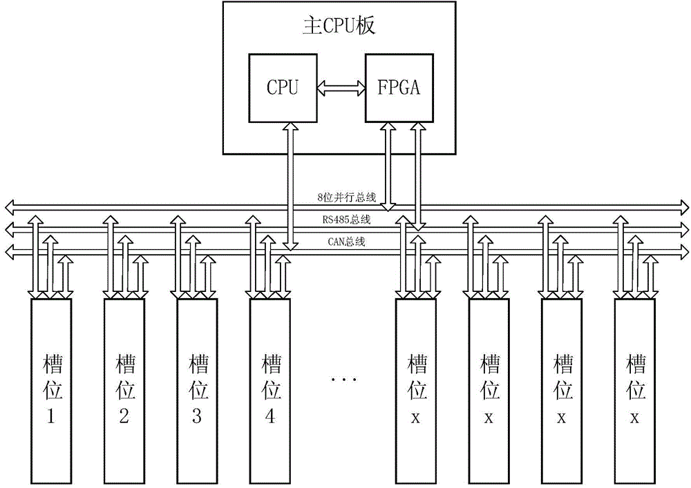
[0028] Such as figure 1 As shown, the present embodiment includes a main CPU board, slots for plug-in boards, three types of bus parallel bus, serial bus and field bus, and the main CPU board includes a CPU module and an FPGA module. These three buses are all connected to the slots. Each slot can use these three buses to send data. Except that the CAN bus is directly connected to the slot by the CPU, the rest are connected to the slot by the FPGA to manage the parallel bus and the RS485 bus in a unified manner.

[0029] Each slot has its own differences, and each slot has a CS chip select line connected to the FPGA, so that the FPGA can time-division multiplex the parallel bus.

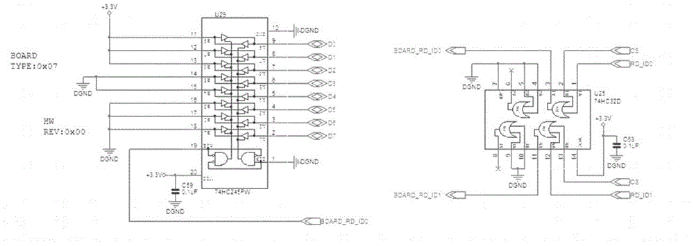
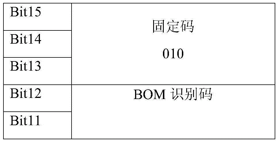
[0030] The parallel bus is composed of CS chip select line, 2 RD_ID, 4 RD, 4 WR and 8 data lines, as shown in Table 1.

[0031] Table 1 Definition table of specific terminals of the bus

[0032]

[0033] The state machine of FPGA reads and writes data through chip select, read and wri...


PUM


Abstract

The invention relates to an FPGA-based (Field Programmable Gate Array-based) IO (Input / Output) bus device with an automatic recognition function, and belongs to the technical field of buses. The IO bus device comprises a CPU (Central Processing Unit), an FPGA, slot position plates, a parallel bus, a serial bus and a field bus, wherein the CPU and the FPGA are used for carrying out data interaction through an external bus, and the FPGA and the slot position plates are interacted through the parallel bus or the serial bus; the CPU and the slot position plates are directly interacted through the field bus; the FPGA is used for providing a plate address for the CPU and helping the CPU to send and receive data, a state machine is arranged in the FPGA, and the state machine can be used for selecting plate interfaces in a circulation mode to read plate information and data signals. The FPGA-based IO bus device has a self-recognition plate information function, so that the reliability of data interaction is enhanced. The communication among plates is more flexible, and upgrading of a device platform is facilitated. The FPGA serves as a bridge of the CPU and external data, and the interaction of plate data is carried out through the serial bus and the parallel bus.

Description

technical field [0001] The invention relates to the field of bus technology, in particular to an expandable power equipment protection device. Background technique [0002] In the traditional power equipment protection device, the connection between the main CPU board and the input, output, analog and other boards uses a dedicated bus, and the data interaction is directly established between the main CPU and various boards. This kind of data transmission This method has many inherent flaws. First of all, this transmission method fixes the position of each board, that is, each board can only be inserted into the fixed position of the backplane, and the connection between the backplane and the main CPU board has been fixed at the beginning of the design. The slots on the board cannot be inserted into other types of boards. Secondly, wrongly inserting boards may cause damage to the device, especially wrongly inserting the wrong power board or analog board may cause damage to ...

Claims


Application Information

Patent Timeline
Patent Type & Authority Applications(China)
IPC IPC(8): G06F13/38G06F13/40
CPCG06F13/385G06F13/4027G06F2213/0002G06F2213/0004G06F2213/3852
Inventor 张杭倪浩
Owner NANJING INTELLIGENT APP
Why Eureka
Try Eureka