Automated bar part machining system and automated bar part machining method by numerical control lathe

A technology of CNC lathes and processing systems, which is applied in the direction of automatic lathes/semi-automatic lathes, metal processing, metal processing equipment, etc. It can solve the problems of labor-consuming and long tool adjustment time, and achieve the effect of avoiding time-consuming and labor-intensive and saving processing time

Inactive Publication Date: 2015-04-08
WUXI TUOFA AUTOMATIC CONTROL EQUIP
View PDF6 Cites 1 Cited by
  • Summary
  • Abstract
  • Description
  • Claims
  • Application Information

AI Technical Summary

Problems solved by technology

This method makes it take a long time to adjust the tool in the processing process, which is time-consuming

Method used


Image

  • Automated bar part machining system and automated bar part machining method by numerical control lathe
  • Automated bar part machining system and automated bar part machining method by numerical control lathe
  • Automated bar part machining system and automated bar part machining method by numerical control lathe

Examples


Embodiment Construction

[0019] The present invention will be further described below in conjunction with specific drawings.

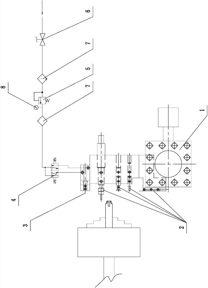
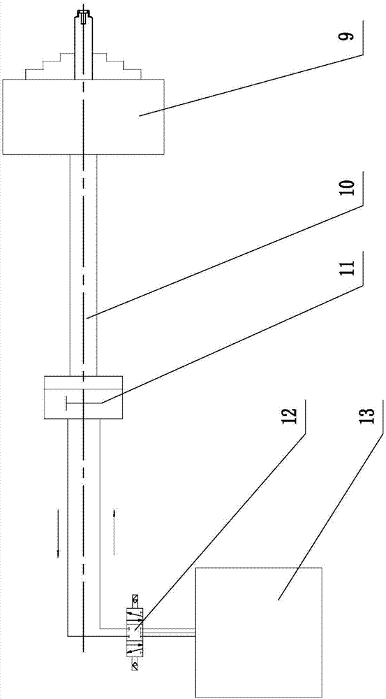
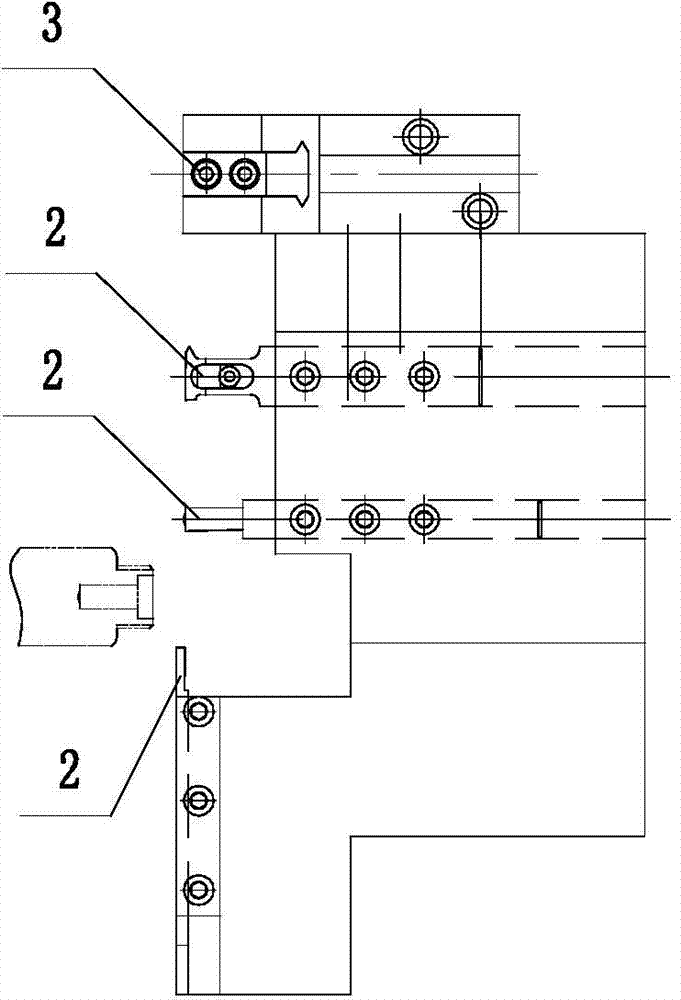
[0020] Such as Figure 1 ~ Figure 4 As shown: the CNC lathe automatic processing system for bar parts includes a tool holder 1, a tool position 2, a manipulator 3, a two-position five-way pneumatic solenoid valve 4, a pressure reducing valve 5, a ball valve 6, a filter 7, and a pressure gauge 8 , Power chuck 9, pull rod 10, oil cylinder 11, three-position five-way hydraulic solenoid valve 12, hydraulic station 13, etc.

[0021] Such as figure 1 As shown, the present invention includes a chuck part and a knife row part, and the knife row part includes a knife rest 1, and a plurality of knife positions 2 are arranged side by side on the knife rest 1, and each knife position 2 is respectively equipped with a corresponding tool, and the knife rest 1 can be positioned at X Move in the direction of the axis and the Z axis to make the tools required for the current process work in ...


PUM


Abstract

The invention relates to an automated bar part machining system and an automated bar part machining method by a numerical control lathe. The automated bar part machining system comprises a chuck portion and a tool array portion, and is characterized in that the tool array portion comprises a tool rest capable of moving in the X-axis direction and the Y-axis direction, the tool rest is provided with a plurality of tool positions side by side, and a manipulator is mounted at one end of the tool rest; the chuck portion is positioned on one side of the X-axis direction and comprises a power chuck for clamping a bar stock. The automated bar part machining method includes the steps of (1), mounting and clamping the bar stock on the power chuck, and clamping the bar stock to pull the same by a certain distance by the manipulator; (2), moving tools to required positions by the tool rest, enabling the power chuck to rotate and using the tools for cutting the bar stock; (3), machining a next part or enabling a spindle to stop rotating, loosening the power chuck and enabling the manipulator to feed. The automated bar part machining system and the automated bar part machining method have the advantages that automated production of the numerical control lathe is achieved truly, so that production efficiency is improved to a greater degree, and labor intensity of workers is reduced.

Description

technical field [0001] The invention relates to a numerically controlled lathe automatic processing system and an automatic processing method for bar parts, belonging to the technical field of automatic processing. Background technique [0002] The CNC lathes currently used can only realize semi-automatic production, especially when using CNC lathes to process parts with long blanks, it is necessary to turn a part and cut it off with a cutter, and then manually pull out a section of blank material It is time-consuming and labor-intensive before restarting the machine tool to process the next part, the processing efficiency is low and the degree of automation of the CNC machine tool is reduced. [0003] In addition, when the existing CNC lathes process long bars, the turret tool holder needs to be continuously rotated according to the process. When the tool needs to be replaced in each process, the turret tool holder must have a rotating action; specifically: turning the end ...

Claims


Application Information

Patent Timeline
IPC IPC(8): B23B11/00B23B21/00B23B15/00B23B31/30B23Q7/04
CPCB23B7/12B23B1/00B23B13/022B23B31/30B23B31/302
Inventor 贺和群张整风李昊李厚伦
Owner WUXI TUOFA AUTOMATIC CONTROL EQUIP
Why Eureka
Try Eureka