

Sealing device for laser welding
A sealing device and laser welding technology, which is applied in laser welding equipment, welding equipment, metal processing equipment, etc., can solve the problems that structural parts cannot withstand pressure, achieve the effect of ensuring sealing effect, uniform pressure distribution, and solving pressure bearing problems
- Summary
- Abstract
- Description
- Claims
- Application Information
AI Technical Summary
Problems solved by technology
Method used
Image

Examples
specific Embodiment approach 1
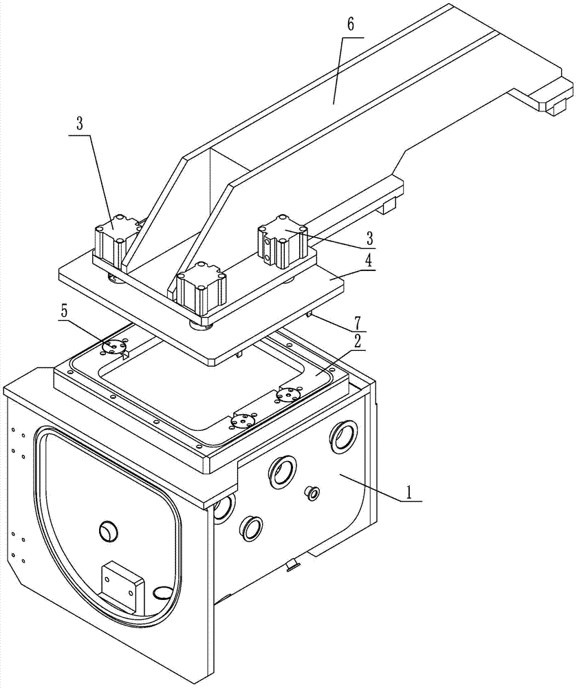
[0008] Specific implementation mode one: combine Figure 1-Figure 3 Explain that the sealing device for laser welding in this embodiment includes a vacuum chamber 1 and a mounting frame 2 for fixing a light-transmitting glass plate, and is characterized in that it also includes a cylinder fixing seat 6, a sealing cover plate 4, and N cylinders 3 , N slide valves 5 and N push rods 7, wherein N is an even number;
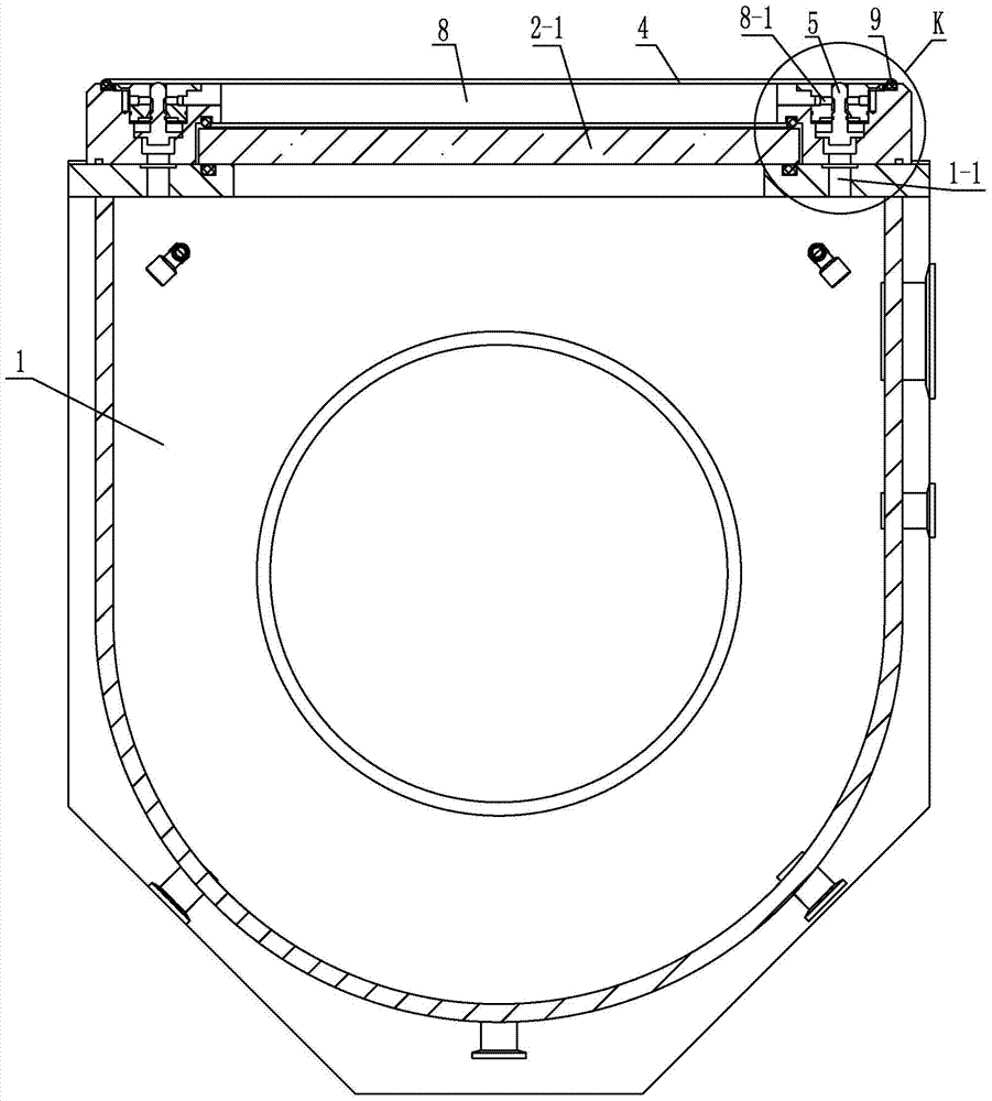
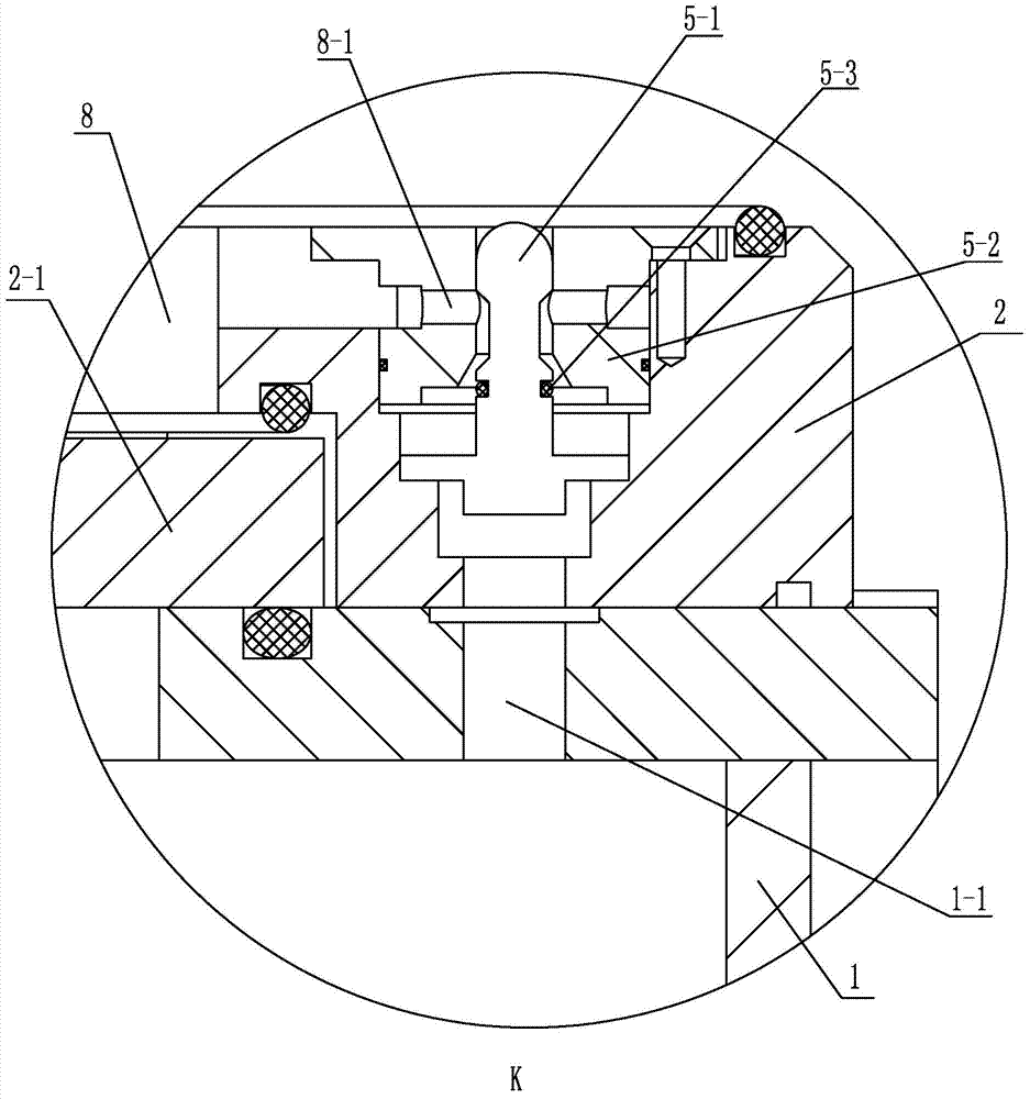
[0009] The middle part of the upper wall of the vacuum chamber 1 is embedded with a mounting frame 2 for fixing a light-transmitting glass plate, and N cylinders 3 are evenly distributed along its circumference on the cylinder fixing seat 6, and the ends of the driving rods of the N cylinders 3 are fixed. On the sealing cover plate 4, the driving direction of the driving rod of the cylinder 3 is downward and perpendicular to the plate surface of the sealing cover plate 4, N slide valves 5 are evenly distributed on the edge of the mounting frame 2 of the fixed transpar...
specific Embodiment approach 2
[0016] Specific implementation mode two: combination figure 1 To illustrate, the number of cylinders 3 in this embodiment is four. With such setting, it is easy to use, and multi-point pressing ensures the sealing effect. Others are the same as in the first embodiment.
specific Embodiment approach 3
[0017] Specific implementation mode three: combination figure 1 and figure 2 Note that the transparent glass plate 2-1 of this embodiment is a cuboid quartz transparent glass plate, the length of the transparent glass plate 2-1 is 355 mm, the width is 335 mm, and the height is 20 mm. With such arrangement, the light-transmitting glass plate is firm, stable and strong. Others are the same as in the first or second embodiment.
PUM
| Property | Measurement | Unit |
|---|---|---|
| Length | aaaaa | aaaaa |
| Width | aaaaa | aaaaa |
| Height | aaaaa | aaaaa |
Abstract
Description
Claims
Application Information