Oil pump shaft machining process

A processing technology, oil pump shaft technology, applied in pumps, components of pumping devices for elastic fluids, pump components, etc., can solve the problem of high hardness of involute splines, poor tooth structure, low processing efficiency, etc. problems, to achieve the effect of eliminating residual stress, good cutting performance, and less tool wear

Inactive Publication Date: 2015-04-08
ZHEJIANG BODA TECH
View PDF6 Cites 23 Cited by
  • Summary
  • Abstract
  • Description
  • Claims
  • Application Information

AI Technical Summary

Problems solved by technology

Although the oil pump shaft after carburizing and quenching treatment has good wear resistance at the contact parts of the deep groove ball bearing 102, oil seal 103 and sliding bearing 104, but the hardness of the involute spline part is high and easy to break, and because the involute Splines are processed by gear hobbing machines or gear shaping machines, which not only has low processing efficiency, but also has poor tooth structure and is not impact resistant, and the teeth of small modulus splines are small. When it is used, it is easy to be interrupted, twisted and deformed, causing the failure of the oil pump

Method used


Image

  • Oil pump shaft machining process
  • Oil pump shaft machining process
  • Oil pump shaft machining process

Examples


Embodiment Construction

[0010] The processing technology of an oil pump shaft of the present invention will be further described below in conjunction with the accompanying drawings and specific embodiments:

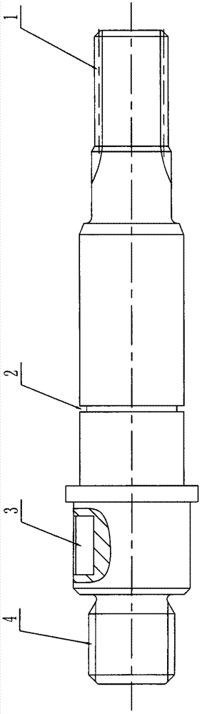
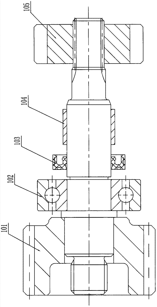
[0011] Such as figure 1 , figure 2 with image 3 As shown, the processing technology of a kind of oil pump shaft of the present invention comprises the following steps:

[0012] Step 1): Use the 42CrMo material blank to blank; Step 2): Use a lathe to turn both ends of the oil pump shaft after step 1), and punch a center hole on both ends; Step 3): Use a lathe to align the warp 2) The outer circle of the processed oil pump shaft is roughly turned, and a margin of 0.5 mm is left on the outer circle and the steps on the outer circle; Step 4): Perform quenching and tempering heat treatment on the oil pump shaft after step 3); Step 5) : Use a lathe to repair and study the center holes on both ends of the oil pump shaft after step 4) heat treatment; Step 6): Use a lathe to carry out the outer circ...


PUM


Abstract

An oil pump shaft machining process includes steps of 1) feeding a blank; 2) turning two end faces and perforating a central hole; 3) roughly turning an outer circle with margin of 0.5 mm; 4) performing quenched-tempered heat treatment; 5) repairing and grinding the central hole; 6) finely turning an outer circle, grooving, turning a thread, and reserving grinding allowance of 0.3 mm after finely turning the outer circle; 7) milling a key slot; 8) cold rolling a spline; 9) locally quenching the outer circle surface at high frequency; 10) annealing at the low temperature, heating to 150-180 DEG C during annealing at the low temperature and preserving temperature for 2.5 hours; 11) repairing and grinding the central hole; 12) finely grinding the outer circles. By the oil pump shaft machining process, contact positions of a machined oil pump shaft with a deep groove ball bearing, an oil seal and a slide bearing are good in wear resistance, and the machined oil pump shaft is high in small-modulus spline machining efficiency, good in tooth form structure, resistant to impact and high in strength.

Description

Technical field: [0001] The invention relates to the field of mechanical parts processing, in particular to a processing technology of an oil pump shaft. Background technique: [0002] The oil pump shaft is subjected to alternating loads, impact loads, and shear stresses during work. The shaft is prone to cracks and wear. It has high requirements for heat treatment, processing technology and materials. Different parts of the shaft have different functions during work, and the processing methods are also different. different. Such as figure 2 As shown, the part of the oil pump shaft where the transmission gear 101 is installed has a keyway, and the part where the rotor 105 is installed has a small modulus spline. larger; and the installation of the deep groove ball bearing 102, the oil seal 103 and the sliding bearing 104 are subject to a larger frictional force. At present, the oil pump shaft is usually made of low carbon steel 20CrMoTi, the spline is usually processed by...

Claims


Application Information

Patent Timeline
Patent Type & Authority Applications(China)
IPC IPC(8): B23P15/00
CPCB23P15/14F04D29/043F05D2230/00F05D2230/10F05D2230/40
Inventor 周金飞石永红周红丽谢振北谢振立
Owner ZHEJIANG BODA TECH
Why Eureka
Try Eureka