
Reduction damping device for elevator

A damping device and elevator technology, which is applied in the field of safety systems for van elevators bottoming out, can solve the problems of passenger danger, accidents, slow hydraulic buffering, etc., and achieve the effect of avoiding secondary rebound and easing buffering

Active Publication Date: 2017-05-24
张家港市欧微自动化研发有限公司
View PDF8 Cites 0 Cited by
  • Summary
  • Abstract
  • Description
  • Claims
  • Application Information

AI Technical Summary

Problems solved by technology

[0003] The uplink and downlink of van elevators are generally achieved by mechanical traction, and the structure is relatively complex. Due to problems such as the use environment, cycle, equipment aging, and quality, it will cause the elevator car to fall without restraint or limited restraint, which is more serious. security issues
In the prior art, in order to solve the serious danger to the passengers caused by the car rigidly touching the bottom (directly falling to the bottom of the hoistway), a buffer device is installed at the bottom of the hoistway; the buffer device is hydraulic buffer for high-speed elevators, and generally adopts The structure of the buffer spring, and this consideration is mainly the relationship between the elastic coefficient of the spring, the stroke and the car. If the elastic force is too large, it will have a greater rebound force and cause greater damage. Therefore, high-speed elevators cannot A spring with a large elastic coefficient is used; in fact, for high-speed elevators, due to the faster speed and the effect of gravity, the buffering of the hydraulic buffer is relatively slow, and serious rigid collisions will still occur, resulting in accidents
[0004] Therefore, it is necessary to improve the existing elevator buffer structure, which is suitable for all van elevators. When the elevator accident bottoms out, it can ensure gentle and gradual compression buffering and return, and avoid excessive elastic coefficient of the buffer spring. Or the safety accident caused by the secondary rebound caused by the compression stroke being too long

Method used


Image

  • Reduction damping device for elevator

Examples


Embodiment Construction

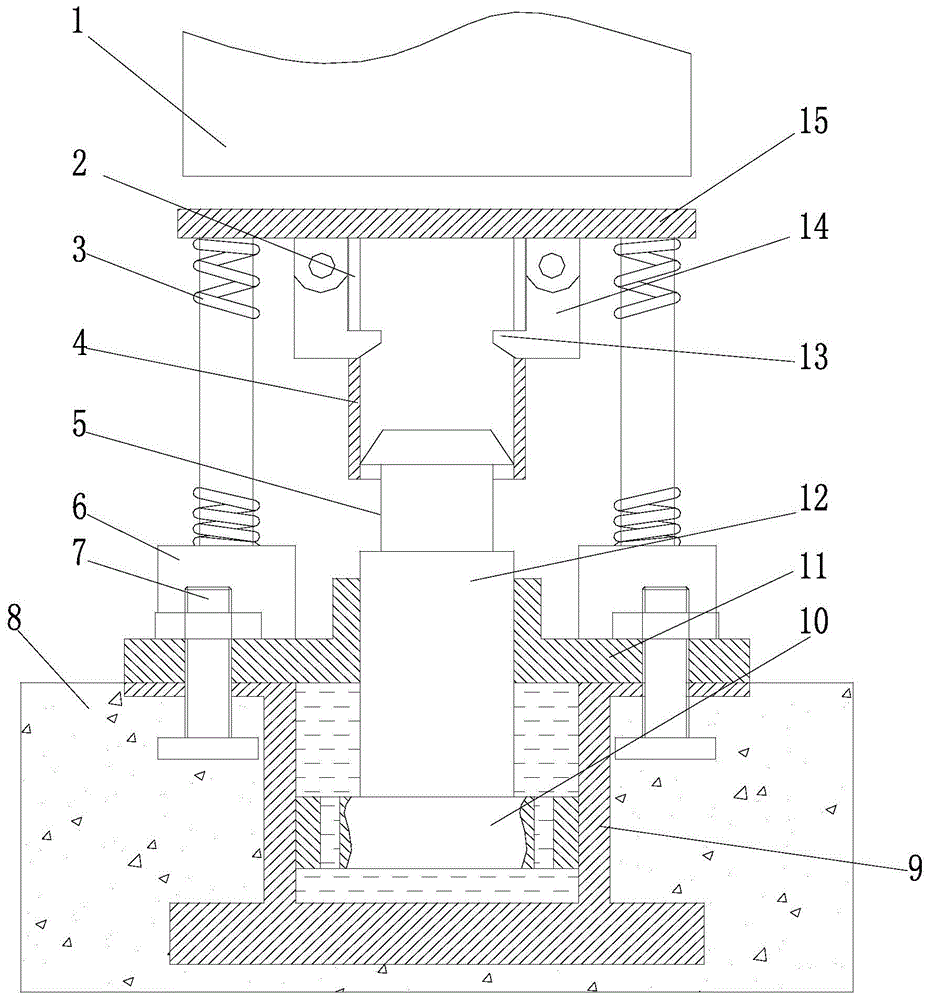
[0017] figure 1 It is a schematic diagram of the structure of the present invention, as shown in the figure: the reduction damping device for an elevator in this embodiment includes a cylinder 9, a damping piston 10 and a piston rod 12 fixedly connected to the damping piston 10, and the piston rod 12 is in The buffer assembly of the elevator is engaged with the buffer assembly between the compression of the elevator car body 1 and the rebound stroke, and the damping piston 10 forms a reduction damping for the buffer assembly. The reduction damping refers to the formation of damping during the reduction deformation after being compressed; the piston The rod 12 can be engaged with the buffer assembly by means of mechanical automatic locking, electromagnetic engagement, etc. Of course, the electromagnetic engagement requires data collection and automatic control, which will not be repeated here; as shown in the figure, the damping piston 10 There is a damping hole (size and quant...


PUM


Abstract

The invention discloses a reduction damping device for an elevator. The reduction damping device comprises a cylinder body, a damping piston and a piston rod, wherein the piston rod is fixedly connected with the damping piston; the piston rod is connected with a buffering component in the stroke that the buffering component of the elevator is compressed by the cage of the elevator and springs back; the buffer buffering component is subjected to reduction damping through the damping piston. Due to adoption of an elevator buffering structure and a reduction damping component which has the function of limiting the resilience speed when the reduction damping component is connected before the buffering to the cage contacting the bottom is finished, the buffering stroke and the elasticity coefficient of the buffering component are greatly increased, relatively gentle buffering can be achieved, rapid resilience can be avoided because of the reduction damping after the buffering, and a final buffering effect is ensured; security accidents caused by secondary resilience caused by too large elasticity coefficient or too long compression stroke of the buffering spring are avoided.

Description

technical field [0001] The invention relates to a safety system for special equipment, in particular to a safety system for a box elevator bottoming out. Background technique [0002] The van elevator is a means of transportation for vertical transportation, which is closely related to people's daily life; the existing van elevator is mainly composed of a traction machine, a control cabinet, a car, guide rails, etc., to achieve relatively rapid up and down ; In order to achieve uplink and downlink and install related equipment, elevator shafts will be built in buildings or other places where van elevators are used to achieve smooth operation. [0003] The uplink and downlink of van elevators are generally achieved by mechanical traction, and the structure is relatively complex. Due to problems such as the use environment, cycle, equipment aging, and quality, it will cause the elevator car to fall without restraint or limited restraint, which is more serious. security issues...

Claims


Application Information

Patent Timeline
Patent Type & Authority Patents(China)
IPC IPC(8): B66B5/28
CPCB66B5/282
Inventor 徐培龙叶敏徐建刘启帆
Owner 张家港市欧微自动化研发有限公司
Learn More