
A balanced solenoid valve with mechanical valve position indicator and manual device

A manual device and indicator technology, applied in the field of solenoid valves, can solve the problems of large volume, large installation space, difficult installation and debugging, etc., and achieve the effect of small volume, small movement friction and smooth movement

Active Publication Date: 2017-01-25
XIAN AEROSPACE YUANZHENG FLUID CONTROL
View PDF5 Cites 0 Cited by
  • Summary
  • Abstract
  • Description
  • Claims
  • Application Information

AI Technical Summary

Problems solved by technology

[0003] At present, the large-diameter solenoid valves on the market are mainly dry-type and split-type valves. The valve body part and the electromagnet part adopt a split structure. The direction of liquid flow and the direction of valve core movement are vertically distributed. Part of it does not contact the medium and has good anti-corrosion performance, but the vertically distributed structure results in a large volume and requires a large installation space
The valve position indicator used is a Hall switch, which is difficult to install and debug, and is not suitable for harsh working conditions.

Method used


Image

  • A balanced solenoid valve with mechanical valve position indicator and manual device
  • A balanced solenoid valve with mechanical valve position indicator and manual device
  • A balanced solenoid valve with mechanical valve position indicator and manual device

Examples


Embodiment Construction

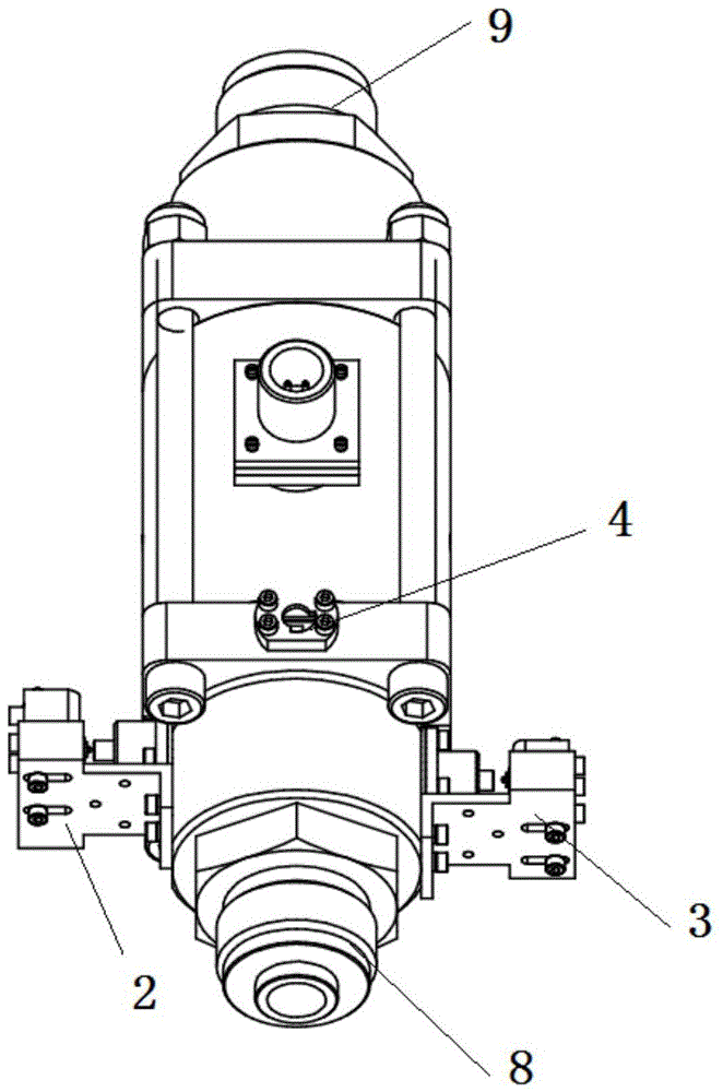
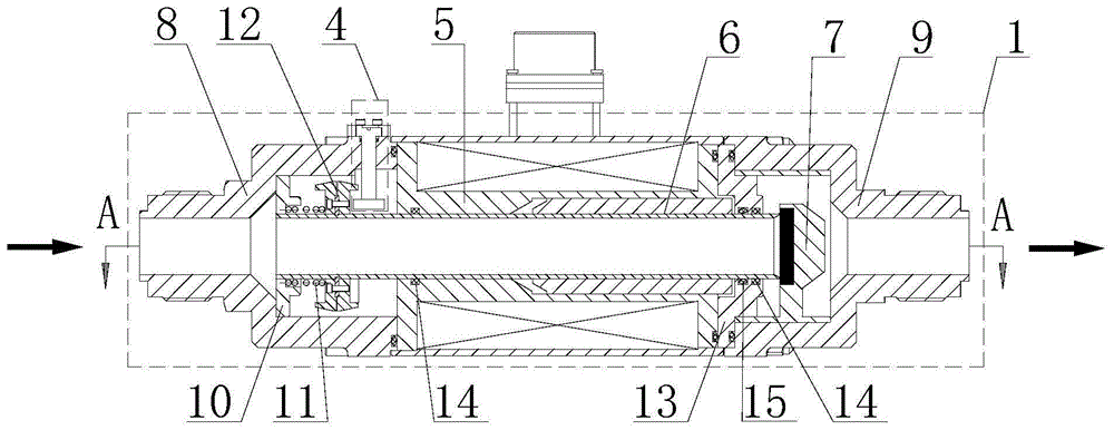
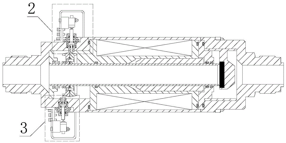
[0024] Such as Figure 1 to Figure 4 As shown, it is a schematic structural diagram of an example of the present invention, which is mainly composed of a main valve 1 , a valve position indicator 2 at a fully closed position, a valve position indicator 3 at a fully open position and a manual device 4 . The main valve 1 includes a coil assembly 5 , a valve core assembly 6 , a valve seat assembly 7 , an inlet flange 8 , an outlet flange 9 , a spring seat 10 , a main spring 11 , a limiting device 12 , and a pressure ring 13 . The system pipeline is respectively connected with the inlet flange 8 and the outlet flange 9; the coil assembly 5 and the valve core assembly 6 form a closed magnetic circuit, and the valve core assembly 6 moves axially guided by the inner hole of the coil assembly 5; the valve core assembly 6 is a split welded structure, which adopts a pressure balance design, and only uses a star-shaped sealing ring 15 to realize dynamic sealing; when the solenoid valve i...


PUM


Abstract

The invention provides a balance type electromagnetic valve with a mechanical valve position indicator and a manual operating device. The balance type electromagnetic valve comprises a main valve, the valve position indicator and the manual operating device, wherein an inlet of the main valve is communicated with a system pressure pipeline; a valve core component is attached to a valve seat component to form seal under the combined action of a main spring and unbalanced force of a medium, and the mechanical valve position indicator provides a closing in-place signal at the time; when the electromagnetic valve is electrified, electromagnetic force acting on the valve core component overcomes the acting force of the main spring and the unbalanced force of the medium to push the valve core component to move, the main valve is opened, and the mechanical valve position indicator provides an opening in-place signal. According to the valve, connection and disconnection of liquid and gas of the pipeline can be realized quickly; the main valve is of the balance type structure, and the unbalanced force of the medium can be effectively reduced; the mechanical valve position indicator is arranged, so the judgment of a working state and fault diagnosis of the electromagnetic valve are facilitated, and conditions are provided for the system to realize automatic control; the manual operating device is arranged, so the valve can be reliably opened under the condition that no power supply or electromagnetic valve fails.

Description

technical field [0001] The invention relates to an electromagnetic valve used for on-off of gas and liquid in a pipeline of a ship system, in particular to a balanced electromagnetic valve with a mechanical valve position indicator and a manual device. Background technique [0002] In the ship system, due to the closed system and intensive space requirements, the requirements for the installation size and automation of system components are relatively high. [0003] At present, the large-diameter solenoid valves on the market are mainly dry-type and split-type valves. The valve body part and the electromagnet part adopt a split structure, and the liquid flow direction is vertically distributed to the valve core movement direction. Part of it does not contact the medium and has good anti-corrosion performance, but the vertically distributed structure results in a large volume and requires a large installation space. The valve position indicator used is a Hall switch, which i...

Claims


Application Information

Patent Timeline
Patent Type & Authority Patents(China)
IPC IPC(8): F16K31/06F16K17/20F16K31/60F16K37/00
CPCF16K31/0655F16K31/60F16K37/0008
Inventor 牟晓勇王兴录杨新峰许长华
Owner XIAN AEROSPACE YUANZHENG FLUID CONTROL
Learn More