

Delay control circuit of DC motor
A time-delay control, DC motor technology, applied in the direction of DC motor speed/torque control, electronic commutation motor control, single motor speed/torque control, etc., can solve the problems of complex control circuit, inconvenient use, and increased cost , to achieve the effect of simple control circuit, cost reduction and equipment safety protection
- Summary
- Abstract
- Description
- Claims
- Application Information
AI Technical Summary
Problems solved by technology
Method used
Image

Examples
Embodiment Construction
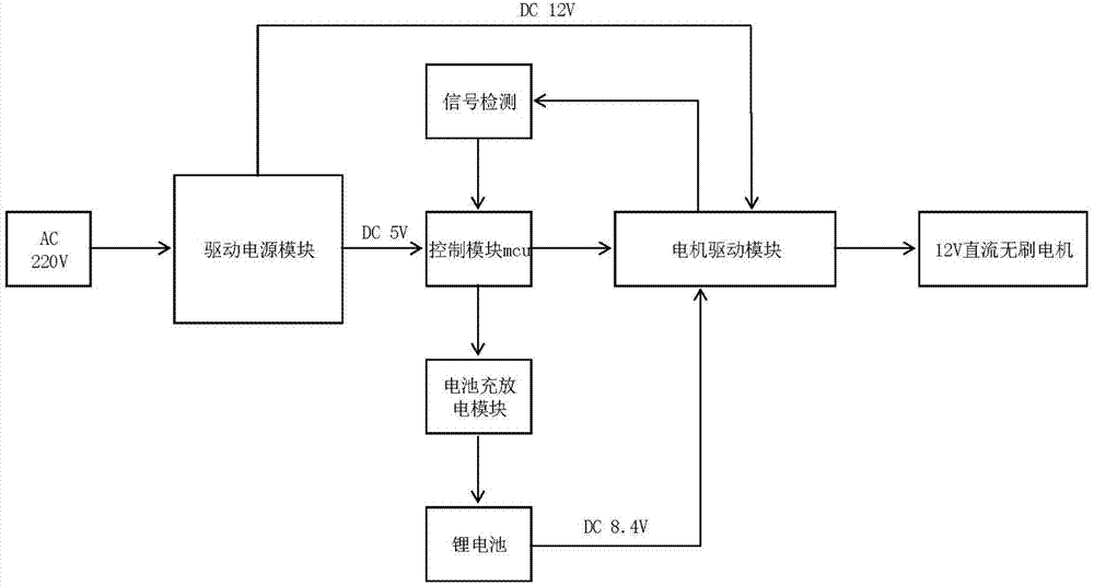
[0026] Such as Figure 1 to Figure 7 As shown, the time-delay control circuit of the DC motor of the present invention includes a driving power supply module for changing AC to DC, a battery charging and discharging module, a motor driving module and a control module MCU, wherein:
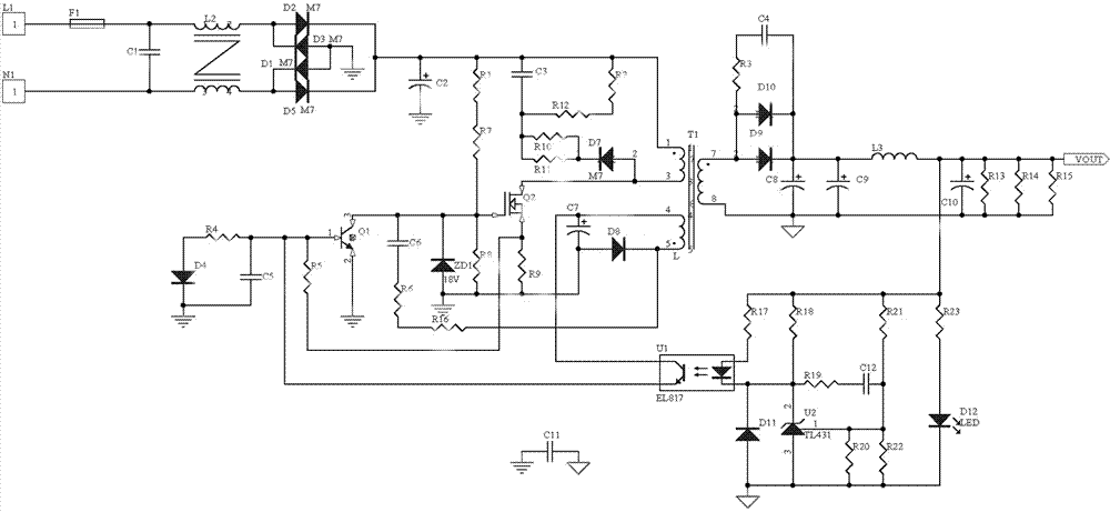
[0027] Such as figure 2 As shown, the driving power supply module of this embodiment includes: 220V AC input from L / N passes through fuse F1, capacitors C1, C2, inductor L2, and diodes D1, D2, D3, D5 rectify and filter to obtain DC voltage. ZD1, D4, D7, R1, R2, R4, R5, R6, R7, R8, R9, R10, R11, R12, C3, C5, C6 and Q1, Q2 form a switching power supply self-excited oscillation circuit, the circuit through the triode The on-state and off-state of Q1 and Q2 control the 1 / 3 pin voltage of the front stage of transformer T1. The step-down rectification filter circuit composed of the secondary 7 / 8 pin of the transformer T1, diodes D9, D10, capacitors C4, C8, C9, C10, inductor L3 and resistors R3, R13, R...
PUM
 Abstract
Description
Claims
Application Information