
Method for manufacturing microwave printed circuit board with step groove

A manufacturing method and step groove technology, which are applied in printed circuit manufacturing, printed circuit, electrical components, etc., can solve the problems that the microstrip pattern microstrip medium at the bottom of the step groove cannot be protected, and the pure polytetrafluoroethylene gasket is easy to fall off, etc. Achieve good glue resistance effect, simple manufacturing process and wide range of materials

Active Publication Date: 2015-04-08
ANHUI SUN CREATE ELECTRONICS
View PDF8 Cites 5 Cited by
  • Summary
  • Abstract
  • Description
  • Claims
  • Application Information

AI Technical Summary

Problems solved by technology

However, due to the non-stickiness of the pure PTFE gasket, the pure PTFE gasket is easy to fall off, and cannot protect the microstrip pattern and the microstrip medium at the bottom of the step groove in the subsequent process

Method used


Image

  • Method for manufacturing microwave printed circuit board with step groove
  • Method for manufacturing microwave printed circuit board with step groove
  • Method for manufacturing microwave printed circuit board with step groove

Examples


Embodiment 1

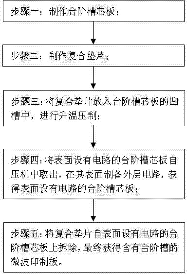
[0030] see figure 1 , a method for manufacturing a microwave printed board containing stepped grooves, the steps are as follows:

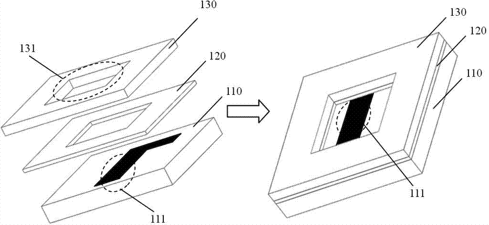
[0031] Step 1: Make the step groove core board. The step groove core plate includes three layers from bottom to top: bottom core plate 110, core plate adhesive film 120 and window layer core plate 130, such as figure 2 shown.

[0032] The bottom core board 110 is a circuit board with a bottom microwave circuit on its surface. The bottom microwave circuit is composed of two parts: a microwave sub-circuit 111 that needs to be exposed and a microwave sub-circuit that does not need to be exposed. The window layer core board 130 is a circuit board with a window 131 on the board, and the window 131 on the window layer core board 130 corresponds to the position of the exposed microwave sub-circuit 111 on the surface of the bottom core board 110 . The core board bonding film 120 is a thin film consistent with the shape of the window layer core board....

Embodiment 2

[0048] see figure 1 , a method for manufacturing a microwave printed board containing stepped grooves, the steps are as follows:

[0049] Step 1: Make the step groove core board. The core plate of the step groove is composed of three layers from bottom to top: the bottom core plate 110, the core plate adhesive film 120 and the window layer core plate 130, as figure 2 shown. The bottom core board 110 is a circuit board with a bottom microwave circuit on its surface. The bottom microwave circuit is composed of two parts: a microwave sub-circuit 111 that needs to be exposed and a microwave sub-circuit that does not need to be exposed. The window layer core board 130 is a multilayer circuit board with a window 131 on the board, and the window 131 on the window layer core board 130 corresponds to the position of the exposed microwave sub-circuit 111 on the surface of the bottom core board 110 . The core board bonding film 120 is a thin film consistent with the shape of the wi...


PUM


Abstract

The invention provides a method for manufacturing a microwave printed circuit board with a step groove. The method comprises the steps: manufacturing a step groove core board; manufacturing a composite spacer; placing the composite spacer in a groove of the step groove core board, and carrying out heating and pressing; taking the step groove core board, of which the surface is provided with a circuit, out of a press, and forming an outer layer circuit on the external surface of a window layer core board, so as to obtain the step groove core board, of which the surface is provided with the circuit; removing the composite spacer from the step groove core board, of which the surface is provided with the circuit, thereby finally obtaining the microwave printed circuit board with the step groove. The method has the beneficial effects that microstrip patterns and microstrip dielectric surface of the bottom of the step groove can be free from any excess resin spill and are free from interference and influence caused by subsequent processing procedures after the microstrip patterns and microstrip dielectric surface of the bottom of the step groove are subjected to press fit; after the processing of the microwave printed circuit board with the step groove is completed and the composite spacer is removed from the step groove, the microstrip patterns and microstrip dielectric surface of the bottom of the step groove do not need any processing, so that the processing efficiency is increased, and the quality of products is improved.

Description

technical field [0001] The invention belongs to the technical field of printed circuit board production, and in particular relates to a method for manufacturing a microwave printed circuit board containing step grooves. Background technique [0002] With the development of microwave communication technology, the demand for multilayer microwave printed boards is increasing year by year. The solder joints of the stripline in the inner layer of the multilayer microwave printed board need to be exposed through the step groove for device welding. It is required that the microstrip pattern at the bottom of the step groove is complete and has excellent solderability, and there is no excess resin residue and other pollutants on the surface of the medium. Affect the electrical performance index. [0003] At present, there are three methods of making step groove microwave plates: [0004] The first method is to use an adhesive film with low resin fluidity, by selecting an adhesive f...

Claims


Application Information

Patent Timeline
Patent Type & Authority Applications(China)
IPC IPC(8): H05K3/00
CPCH05K3/4602H05K2203/13
Inventor 朱正大管美章陈彦青贾亮范晓春
Owner ANHUI SUN CREATE ELECTRONICS
Learn More