Motor vehicle engine cooling system and method

A technology for cooling systems and motor vehicles, applied in the direction of engine cooling, machine/engine, engine components, etc., capable of solving problems such as harmful effects on engine performance and service life

Inactive Publication Date: 2015-04-08
JAGUAR LAND ROVER LTD
View PDF4 Cites 33 Cited by
  • Summary
  • Abstract
  • Description
  • Claims
  • Application Information

AI Technical Summary

Problems solved by technology

[0007] A second problem associated with the arrangement of Figure 1 is that if the coolant temperature oscillates (due to oscillations in the state of the top valve TV) while the block valve BV is op

Method used


Image

  • Motor vehicle engine cooling system and method
  • Motor vehicle engine cooling system and method
  • Motor vehicle engine cooling system and method

Examples


Embodiment Construction

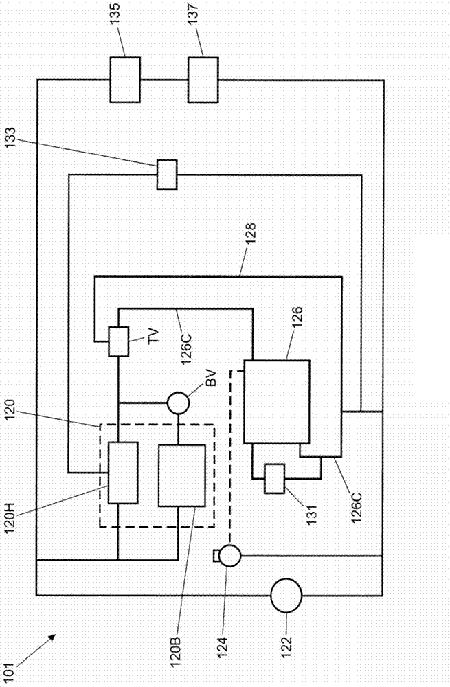
[0089] figure 2 is a schematic diagram of a coolant circuit 201 which is not a circuit according to an embodiment of the invention. The circuit 201 is coupled to the engine 220 and arranged to provide coolant flow through the engine 220 .

[0090] The engine 220 has a cylinder head portion 220H and a cylinder block portion 220B. An engine driven coolant pump 222 is provided to pressurize the coolant and deliver the pressurized coolant to the coolant inlets of the cylinder head portion 220H and the cylinder block portion 220B of the engine 220 .

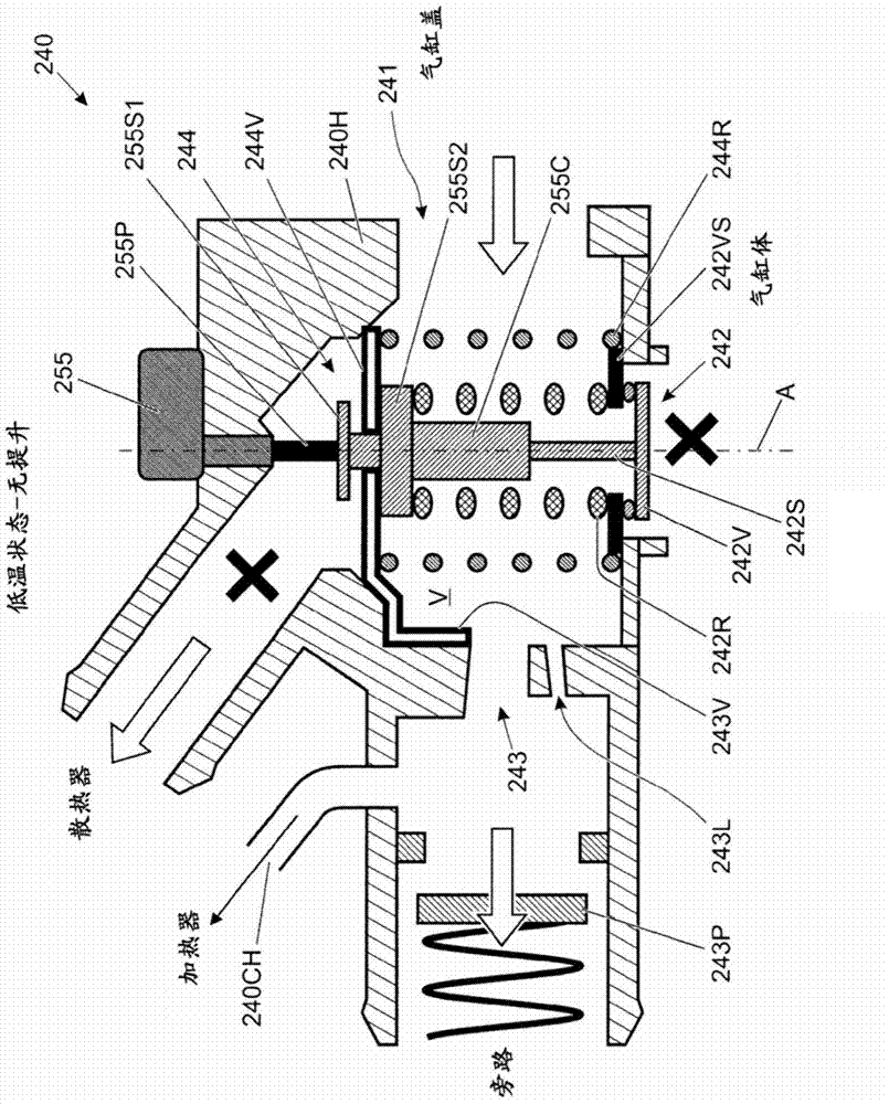
[0091] The coolant outlet of each of the cylinder head portion 220H and the cylinder block portion 220B is coupled to a corresponding inlet of an integrated valve assembly (IVM) 240 . The IVM 240 has three outlets: radiator flow outlet 240R; radiator bypass flow outlet 240B; and cabin heater flow outlet 240CH. In some arrangements no cabin heater flow outlet 240CH is provided.

[0092] Radiator flow outlet 240R is coupled to radia...


PUM


Abstract

The device has a valve including a closure member 344V that opens and closes in response to a temperature of coolant flowing through the device. When moving from a closed position to an open position, the member moves in a direction downstream of the direction of coolant flow through the device. A vehicle engine cooling system comprising the device is also claimed. When claimed as part of the vehicle engine cooling system, the device additionally comprises a first inlet 341 connected to a cylinder head of the engine, a second inlet 342 connected to a cylinder block of the engine, a first outlet 343 connected to a radiator bypass conduit and a second outlet 344 connected to a radiator, whereby the valve is associated with the second outlet. The closure member may automatically open when a pressure differential across the valve exceeds a predetermined value. The system may include a variable speed coolant pump controlled based upon at least one vehicle operating parameter, such as the temperature of coolant, engine/transmission oil, or engine speed, that pumps coolant in the system at two different non-zero rates, the higher rate causing opening of the valve. A method is also claimed.

Description

technical field [0001] The present invention relates to an apparatus for controlling fluid flow in an engine coolant system. In particular, but not exclusively, the invention relates to engine coolant flow control in motor vehicles. Background technique [0002] It is known to provide an engine cooling arrangement for cooling an engine of a motor vehicle. FIG. 1 is a schematic diagram of a known coolant circuit connected to an engine 120 . The apparatus has an engine driven fluid pump 122 arranged to pump coolant through the cylinder head 120H of the engine 120 and optionally through the cylinder block 120B of the engine 120 depending on the state of the cylinder block flow valve BV . A block flow valve BV is provided at the outlet of the cylinder block 120B. The block flow valve BV is configured to open when the temperature of a portion of the block flow valve BV exceeds a prescribed value, thereby allowing coolant to flow through the block 120B. [0003] Additional me...

Claims


Application Information

Patent Timeline
IPC IPC(8): F01P7/16
CPCF01P7/165F01P2005/125F01P2003/027F01P2007/146F01P3/02F01P7/16
Inventor 威廉·哈钦斯
Owner JAGUAR LAND ROVER LTD
Why Eureka
Try Eureka