Oil distribution disc and cylinder block assembly of hydraulic pump and machining method thereof

An oil distribution plate and hydraulic pump technology, applied in the field of hydraulic pumps, can solve problems such as noise pollution, locking, and too small assembly clearance, and achieve the effects of improving work efficiency, preventing mechanical damage, and ensuring transmission performance

Inactive Publication Date: 2015-04-15
HUNAN AGRICULTURAL UNIV
View PDF4 Cites 2 Cited by
  • Summary
  • Abstract
  • Description
  • Claims
  • Application Information

AI Technical Summary

Problems solved by technology

However, in the hydraulic pump oil distribution plate cylinder assembly currently used, the design of the cylinder block and the oil distribution plate is unreasonable, which brings great difficulties to the assembly, and easily causes the assembly clearance to be too small or locked, resulting in mechanical damage, while the assembly clearance If it is too large, it will inevitably affect the volumetric efficiency of the pump; in addition, the oil distribution plate is prone to vibration during the oil suction process, which not only causes noise pollution, but also affects the characteristics of the hydraulic system

Method used


Image

  • Oil distribution disc and cylinder block assembly of hydraulic pump and machining method thereof
  • Oil distribution disc and cylinder block assembly of hydraulic pump and machining method thereof
  • Oil distribution disc and cylinder block assembly of hydraulic pump and machining method thereof

Examples


Embodiment Construction

[0041] In order to make the technical means, creative features, goals and effects achieved by the present invention easy to understand, the present invention will be further described below in conjunction with specific illustrations.

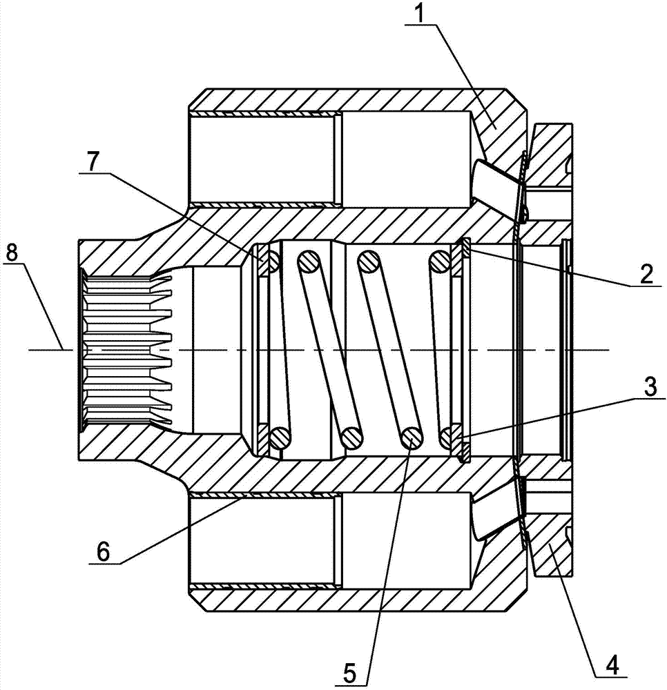
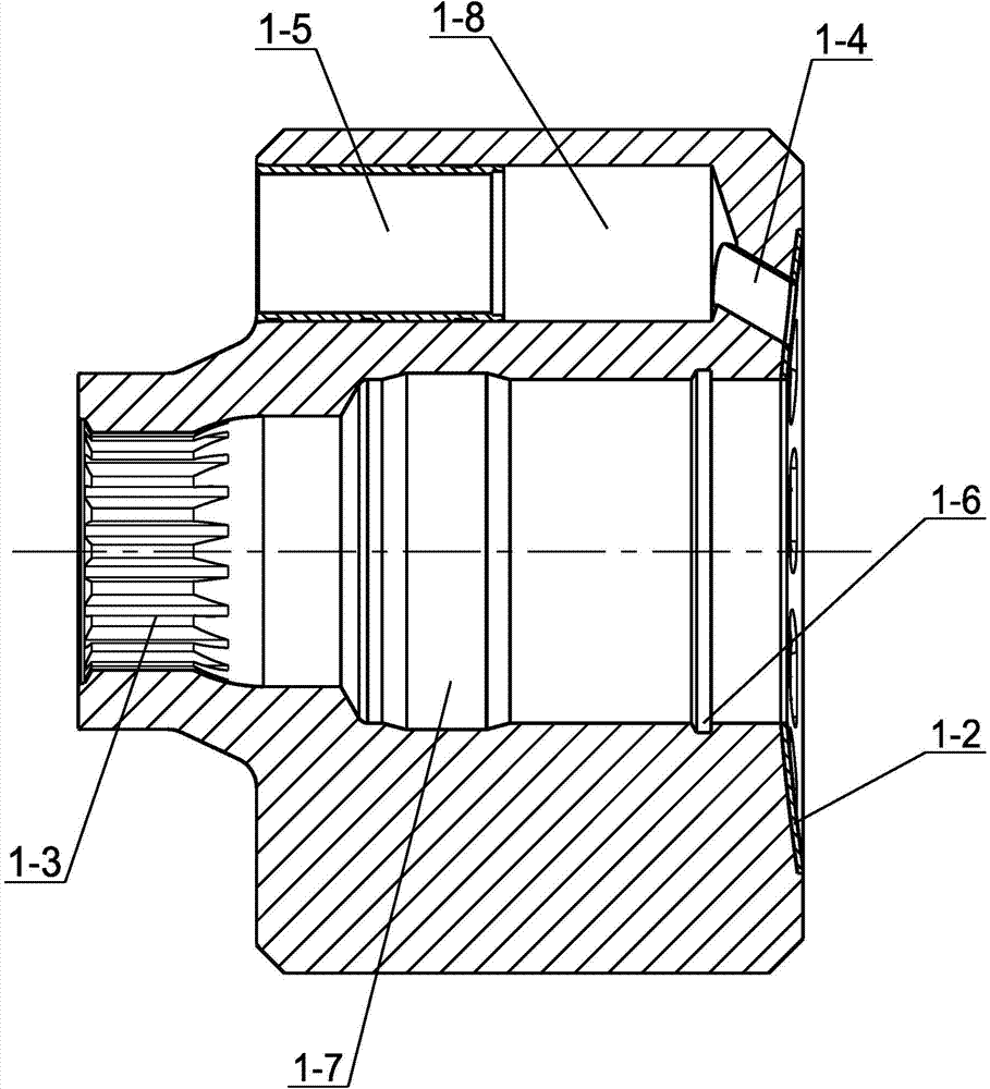
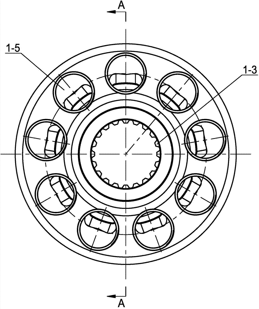
[0042] see Figure 1 to Figure 10 Hydraulic pump oil distribution plate cylinder assembly, including cylinder body 1, hole opening retaining ring 2, retaining ring 3, oil distribution plate 4, spring 5, cylinder liner 6, gasket 7, cylinder rotation center 8, main body blank 1 -1, Cylinder body welded copper 1-2, transmission inner spline 1-3, cylinder body oil passage 1-4, cylinder liner inner hole 1-5, retaining ring inner groove 1-6, cylinder body rotary cavity 1- 7. Plunger pressure oil cavity 1-8, inner circle relief groove 4-1, matching inner hole 4-2, first suction oil waist hole 4-3, second suction oil waist hole 4- 4. The circumferential positioning pin holes 4-5, the first damping groove 4-6 and the second damping groove 4-7.

[0043]...


PUM


Abstract

The invention discloses an oil distribution disc and cylinder body assembly of a hydraulic pump. The oil distribution disc and cylinder body assembly includes a cylinder body and an oil distribution disc, wherein the cylinder body is sintered on a main body workblank by welding copper, and an internal transmission spline is arranged at the center of the cylinder body; the cylinder body is matched with the oil distribution disc by spherical surfaces, for improving work efficiency of the oil distribution disc; meanwhile, a cylinder body rotating cavity is arranged in the cylinder body, a spring is installed in the cylinder body rotating cavity, thus being beneficial to form fitting of the cylinder body and the oil distribution disc; a plunger oil pressing cavity is arranged at the periphery of the cylinder body rotating cavity, a cylinder sleeve is installed in the plunger oil pressing cavity in a pressing manner, and a plunger is installed in the hole of the cylinder sleeve; the oil distribution disc is cooperatively installed on the valve body of the hydraulic pump, and an inner circle tool relief groove is arranged on the oil distribution disc; in addition, the oil distribution plate is provided with a first kidney-shaped oil sucking and pressing hole and a second kidney-shaped oil sucking and pressing hole, a vibration damping groove is arranged on the side of each of the first and second kidney-shaped oil sucking and pressing holes, for cooperatively sucking and pressing oil, and reducing vibration; the plunger oil pressing cavity is communicated with the first and second kidney-shaped oil sucking and pressing holes by cylinder body oil paths.

Description

technical field [0001] The invention relates to the technical field of hydraulic pumps, in particular to a hydraulic pump oil distribution plate cylinder assembly and a processing method thereof. Background technique [0002] The plunger hydraulic pump relies on the change of the closed volume formed by the reciprocating movement of the plunger in the cylinder to realize oil suction and oil pressure. Compared with other pumps, it has high working efficiency, high pressure, long service life, and convenient flow adjustment. The power and weight are small, so it is widely used in the field of mechanical equipment. However, in the hydraulic pump oil distribution plate cylinder assembly currently used, the design of the cylinder block and the oil distribution plate is unreasonable, which brings great difficulties to the assembly, and easily causes the assembly clearance to be too small or locked, resulting in mechanical damage, while the assembly clearance If it is too large, i...

Claims


Application Information

Patent Timeline
Patent Type & Authority Applications(China)
IPC IPC(8): F04B53/16F04B53/00
Inventor 张祝沈陆明陈力航周光永童成前张同虎
Owner HUNAN AGRICULTURAL UNIV
Why Eureka
Try Eureka