X-ray inspection system

An inspection system and X-ray technology, applied in the field of X-ray applications, can solve the problems of affecting the monitoring effect, mechanical deformation interference, weak X-ray beam intensity, etc., and achieve accurate and reliable monitoring results

Active Publication Date: 2015-04-15
TSINGHUA UNIV +1
View PDF11 Cites 4 Cited by
  • Summary
  • Abstract
  • Description
  • Claims
  • Application Information

AI Technical Summary

Problems solved by technology

[0010] In the dose monitoring device of the prior art, the X-ray beam intensity is lost due to the need to penetrate the sensitive volume of the detection module, that is, the detection sensitive volume interferes with the X-ray beam intensity and energy spectrum structure reaching the object under inspection
And because the electron accelerator is a strong electric device, and the detection module of the dose monitoring device is a weak electric device, the detection module is very susceptible to the electromagnetic interference of the former, and generally can only provide average dose information within a period of time, such as a few seconds
In order to ensure safety in the X-ray inspection system, when the dose of the X-ray beam current is greater than the prescribed threshold, the power supply of the X-ray emitting device must be cut off as soon as possible, so the dose monitoring device must be reliable and accurate, and the above prior art It is difficult for a dose monitoring device to meet this requirement
[0011] In the brightness monitoring device of the prior art, the redundant detectors of the detector array are easily interfered by factors such as reflected signals and mechanical deformation of the inspected object
And when the X-ray emitting device is an electron accelerator, in the direction of the "main beam" of the X-ray beam (that is, the direction of the electron beam), the intensity of the X-ray beam is high, and the position where the angle between the "main beam" and the "main beam" is larger The weaker the X-ray beam intensity, the weaker the X-ray beam intensity in the area where the redundant detector is located, which ultimately affects the monitoring effect

Method used


Image

  • X-ray inspection system
  • X-ray inspection system
  • X-ray inspection system

Examples


no. 1 example

[0049] Figure 1 to Figure 5 An X-ray inspection system of a first embodiment of the present invention is shown.

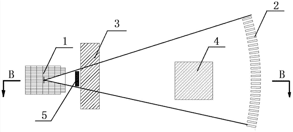
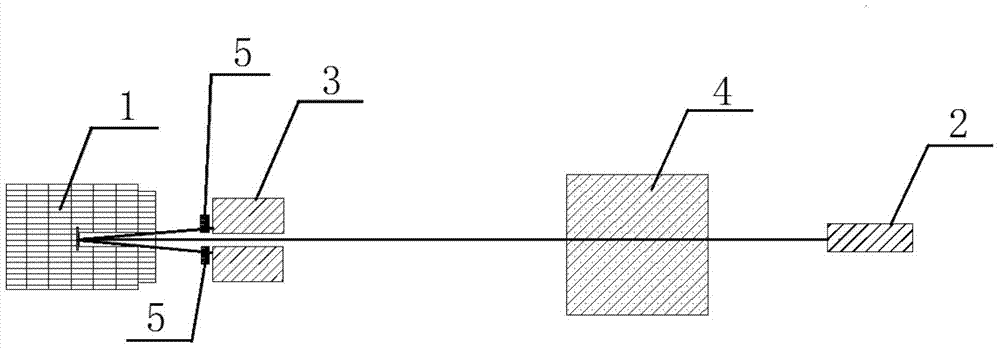
[0050] figure 1 It is a schematic layout diagram of the X-ray inspection system according to the first embodiment of the present invention. figure 2 for figure 1 The BB-direction sectional schematic diagram of the X-ray inspection system shown. Such as figure 1 and figure 2 As shown, the X-ray inspection system of the first embodiment includes an X-ray emitting device for emitting X-rays, a collimator 3, a detector array 2 for X-ray inspection, and an X-ray beam intensity monitoring device. Wherein the X-ray beam intensity monitoring device is used for monitoring the X-ray beam intensity of the X-ray emitting device.

[0051] The X-ray beams emitted by the X-ray emitting device include working beams irradiated on the detector array 2 and redundant beams irradiated outside the detector array 2 .

[0052] In the first embodiment, the X-ray emitting device i...

no. 2 example

[0074] The difference between the second embodiment and the first embodiment is that in the second embodiment, the gas detection module 6 replaces the scintillation detection module 5 of the first embodiment as the intensity detection module. Wherein, the left detection module and the right detection module each use a gas detection module 6 with the same structure to detect the intensity of the X-ray beam.

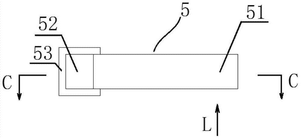
[0075] Figure 6 It is a schematic diagram of the structural principle of the intensity detection module of the X-ray beam intensity monitoring device in the X-ray inspection system according to the second embodiment of the present invention. Figure 7 for Figure 6 The schematic diagram of the structural principle of the intensity detection module when it is perpendicular to the X-ray fan-shaped beam is shown. Figure 6 and Figure 7 The working principle of the intensity detection module of the second embodiment will be described by taking one of the left detection mo...


PUM


Abstract

The invention discloses an X-ray inspection system which comprises an X-ray transmitting device, a detector array and an X-ray beam intensity monitoring device, wherein an X-ray beam emitted by the X-ray transmitting device comprises a working beam irradiated on the detector array and a redundancy beam irradiated beyond the detector array; the X-ray beam intensity monitoring device comprises an intensity detection module and a data processing module; the intensity detection module is arranged between the X-ray transmitting device and the detector array to receive irradiation of the redundancy beam and emit a detection signal; the data processing module is coupled with the intensity detection module to receive the detection signal and output an X-ray beam intensity monitoring signal. The intensity detection module of the X-ray inspection system utilizes the redundancy beam of the X-ray beam, and is not influenced by the X-ray transmitting device and an object to be inspected basically, so that a monitoring result of X-ray beam intensity can be more accurate and reliable.

Description

technical field [0001] The invention relates to the technical field of X-ray applications, in particular to an X-ray inspection system. Background technique [0002] In the X-ray inspection system, the X-ray emitting device is mainly an electron accelerator or an X-ray tube. The X-ray emitting device and the detector array for X-ray inspection are placed on both sides of the inspected object. Generally, the X-ray beams emitted by the X-ray emitting device include working beams directly irradiated on the detector array and redundant beams irradiated outside the detector array. [0003] The X-ray beam is usually a fan-shaped beam, and the fan-shaped beam is perpendicular to the ground. In the fan-shaped beam, the width of the working beam at the detector array is generally required to be approximately equal to the width of the detector array. For this purpose, a collimator is often arranged between the x-ray emission device and the detector array. The collimator is used to ...

Claims


Application Information

Patent Timeline
Patent Type & Authority Applications(China)
IPC IPC(8): G01N23/02
Inventor 李树伟张清军康克军李元景李玉兰赵自然刘以农刘耀红朱维彬赵晓琳何会绍
Owner TSINGHUA UNIV
Why Eureka
Try Eureka