
Steam-turbine generator retaining ring ultrasonic imaging testing method

A technology of ultrasonic imaging detection and turbogenerator, which is applied in the direction of using sound wave/ultrasonic wave/infrasonic wave to analyze solids. Echo and defect echo, overcoming the complexity of detection steps, the effect of reliable non-destructive testing

Inactive Publication Date: 2015-04-15
STATE GRID HENAN ELECTRIC POWER ELECTRIC POWER SCI RES INST +2
View PDF1 Cites 7 Cited by
  • Summary
  • Abstract
  • Description
  • Claims
  • Application Information

AI Technical Summary

Problems solved by technology

Due to the special sound wave propagation performance and complex shape of the material of the turbogenerator guard ring, it is often easily affected by factors such as inherent echoes during A-type pulse reflection contact ultrasonic testing, resulting in misjudgment or missed detection of defects
On the other hand, due to the interference fit used in the assembly of the turbogenerator retaining ring, the shaft teeth have symmetrical indentations on the inner surface of the embedded part, so it is easy to form a reflection when using the traditional A-type pulse reflection contact ultrasonic detection. , causing misjudgment
With the increase of power plant unit capacity, there are more and more types of turbo generator guard rings. The existing detection methods have been Unable to meet the detection requirements of various types of turbo generator guard rings

Method used


Image

  • Steam-turbine generator retaining ring ultrasonic imaging testing method
  • Steam-turbine generator retaining ring ultrasonic imaging testing method

Examples


Embodiment Construction

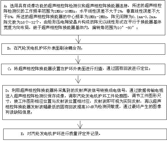
[0018] Such as figure 1 As shown, the ultrasonic imaging detection method of the turbogenerator retaining ring of the present invention comprises the following steps in turn:

[0019] A: Choose an ultrasonic phased array detector with imaging function and connect it with an ultrasonic phased array transducer. The linear error is not more than 8%; the center frequency of the ultrasonic phased array transducer is 1MHz-2MHz, the array element gap is 0.1mm-0.2mm, the number of array elements is 16-32, and it is made of rectangular piezoelectric ceramics The array elements composed of wafers are laid out in a linear form parallel to the width of the transducer substrate, embedded in the ultrasonic phased array transducer substrate, and the deflection angle ranges from 10° to 80°;

[0020] B: Brush the coupling agent on the outer surface of the turbine generator retaining ring;

[0021] C: Set the ultrasonic phased array transducer on the outer surface of the guard ring for scanni...


PUM


Abstract

The invention discloses a steam-turbine generator retaining ring ultrasonic imaging testing method which comprises the following steps: A, an ultrasonic phased array testing instrument and an ultrasonic phased array transducer are connected; B, the outer surface of a steam-turbine generator retaining ring is brushed and coated with a coupling agent; C, the ultrasonic phased array transducer is arranged on the outer surface of the steam-turbine generator retaining ring for scanning, and is located by an inherent echo; D, collected reflected acoustic signals are converted into electrical signals by the ultrasonic phased array transducer, and are stored and imaged by the ultrasonic phased array testing instrument, a steam-turbine generator retaining ring workpiece contour diagram is taken, workpiece contour diagram corresponding positions are corresponding to reflected wave positions, the ultrasonic phased array transducer transmits the inherent echo with lowest amplitude, the inherent echo is increased by 10 db to use as detection sensitivity, and the defect information can be interpreted through a generated image; and E, quality of the steam-turbine generator retaining ring is assessed and recorded. The steam-turbine generator retaining ring ultrasonic imaging testing method has the advantages of capability of convenient and quick nondestructive detection of internal defects of the steam-turbine generator retaining ring, and accurateness and effectiveness.

Description

technical field [0001] The invention relates to a detection method for a turbogenerator guard ring, in particular to an ultrasonic imaging detection method for a turbogenerator guard ring. Background technique [0002] Turbogenerators are widely used in electric power enterprises. At present, when testing the guard rings of turbogenerators, the A-type pulse reflection contact ultrasonic testing method is mainly used. Due to the special sound wave propagation performance and complex shape of the material of the turbogenerator guard ring, it is often easily affected by inherent echo and other factors when performing A-type pulse reflection contact ultrasonic testing, which leads to misjudgment or missed detection of defects. On the other hand, due to the interference fit used in the assembly of the turbogenerator retaining ring, the shaft teeth have symmetrical indentations on the inner surface of the embedded part, so it is easy to form a reflection when using the traditional...

Claims


Application Information

Patent Timeline
Patent Type & Authority Applications(China)
IPC IPC(8): G01N29/06
Inventor 靳峰李世涛汪毅蔡红生吴克华
Owner STATE GRID HENAN ELECTRIC POWER ELECTRIC POWER SCI RES INST
Learn More