
Method for forming CMOS transistor

A transistor and semiconductor technology, applied in semiconductor devices, semiconductor/solid-state device manufacturing, electrical components, etc., to improve performance, reduce etching time, and improve efficiency

Active Publication Date: 2015-04-15
SEMICON MFG INT (SHANGHAI) CORP
View PDF5 Cites 9 Cited by
  • Summary
  • Abstract
  • Description
  • Claims
  • Application Information

AI Technical Summary

Problems solved by technology

[0004] The performance of the CMOS transistors formed by the prior art still needs to be further improved

Method used


Image

  • Method for forming CMOS transistor
  • Method for forming CMOS transistor
  • Method for forming CMOS transistor

Examples


Embodiment Construction

[0029] As mentioned in the background art, the performance of the CMOS transistors formed in the prior art still needs to be further improved.

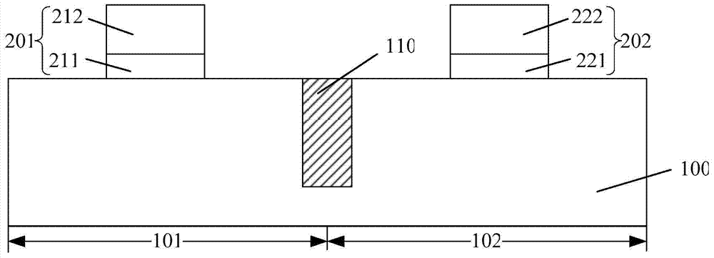
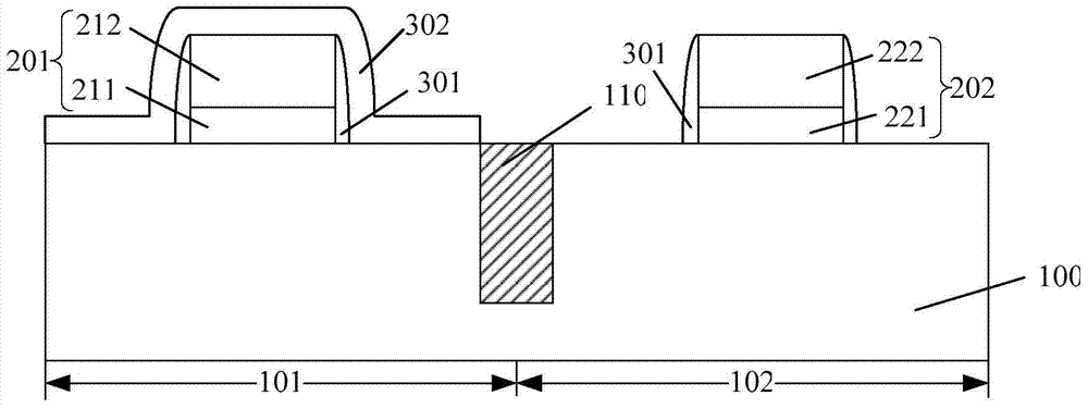
[0030] In the process of forming a CMOS transistor using the "gate-last" process, in order to improve the performance of the PMOS transistor in the CMOS transistor, it is necessary to form grooves in the source and drain regions of the semiconductor substrate on both sides of the dummy gate structure on the PMOS region, and then form grooves in the PMOS region. The groove is filled with SiGe as the source and drain; before the groove is formed in the source and drain regions of the PMOS region, a hard mask layer needs to be formed on the surface of the NMOS region to protect the groove during the formation of the groove. NMOS region, and subsequently retain the part of the hard mask layer on the top and both sides of the dummy gate structure of the NMOS region when forming the source and drain regions of the NMOS region, as a mask when...


PUM


Abstract

A method for forming a CMOS transistor comprises the following steps: providing a semiconductor substrate consisting of a first region and a second region, wherein a first dummy gate structure, first spacers on the two side surfaces of the first dummy gate structure and a first hard mask layer on the first dummy gate structure are formed on the first region, and a second dummy gate structure and second spacers on the two side wall surfaces of the second dummy gate structure are formed on the second region; forming a second hard mask layer; forming a filling layer covering the second hard mask layer and a mask layer disposed on part of the surface of the filling layer on the second region on the surface of the semiconductor substrate; etching a partial thickness of the filling layer on the first region and part of the second hard mask layer on the top of the first dummy gate structure; and removing the filling layer, the mask layer and the second hard mask layer, and forming a first stress layer covering the first dummy gate structure and a second stress layer covering the second dummy gate structure. By adopting the method of the invention, the performance of a formed CMOS transistor can be improved.

Description

technical field [0001] The invention relates to the technical field of semiconductors, in particular to a method for forming a CMOS transistor. Background technique [0002] With the rapid development of semiconductor manufacturing technology, semiconductor devices are developing toward higher component density and higher integration in order to achieve higher computing speed, larger data storage capacity, and more functions. In order to obtain better electrical performance, it is usually necessary to improve the performance of semiconductor devices by controlling the carrier mobility. A key element in controlling carrier mobility is controlling the stress in the transistor channel to increase the drive current. At present, the embedded silicon germanium (Embedded GeSi) technology is used, that is, the silicon germanium material is first formed in the area where the source region and the drain region need to be formed, and then doped to form the source region and the drain ...

Claims


Application Information

Patent Timeline
IPC IPC(8): H01L21/8238
CPCH01L29/66545H01L29/165H01L29/665H01L29/6656H01L29/66636H01L29/7843H01L29/7848H01L21/823892H01L21/823864
Inventor 何永根
Owner SEMICON MFG INT (SHANGHAI) CORP
Learn More