Charging configuration for the inductive wireless emission of energy
A charging device and a technology for releasing energy, applied in circuit devices, battery circuit devices, charging stations, etc., can solve the problems of small magnetic flux density, difficult to install vehicles, etc.
- Summary
- Abstract
- Description
- Claims
- Application Information
AI Technical Summary
Problems solved by technology
Method used
Image

Examples
Embodiment Construction
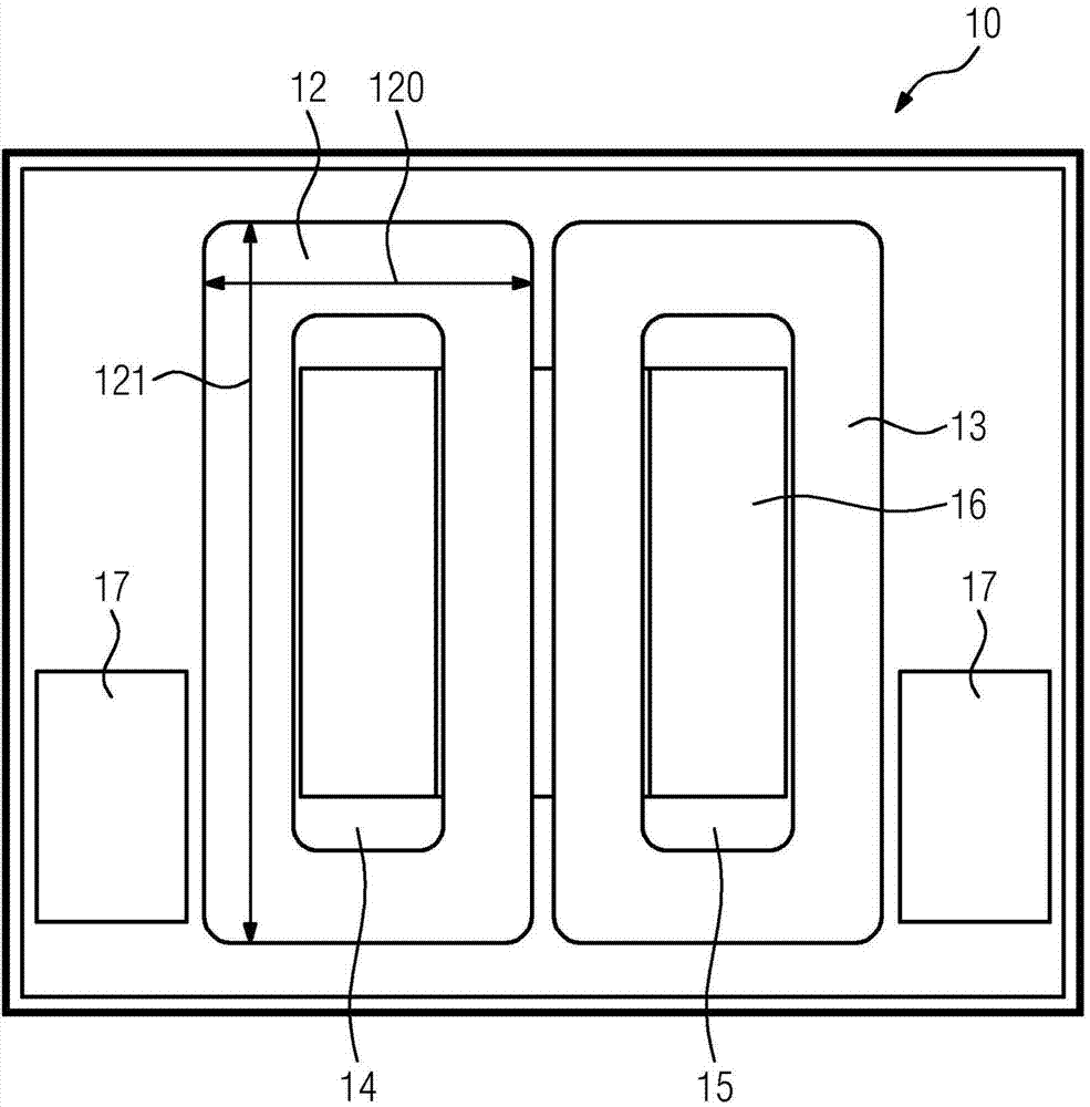
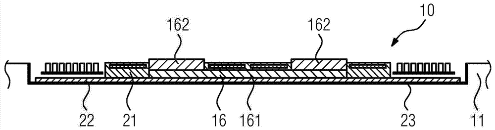
[0025] These figures show a ground-mounted charging device 10 for an electric vehicle for the inductive discharge of energy. Energy is received by coils on the vehicle side, not shown. The ground-side charging device 10 is installed in the ground 11 . figure 1 shows a view from above of the part, while figure 2 A side view of the components is shown.
[0026] The charging device 10 arranged on the ground side comprises a first coil 12 and a second coil 13 arranged coplanarly. The two coils 12 , 13 are of equal size and basically of the same type. The coils 12, 13 are each wound in one plane, ie without helical properties. The two coils 12 , 13 are rectangular coils, ie the conductor tracks of the coils 12 , 13 run straight up to the vicinity of the corners of the respective coil 12 , 13 and are then bent through 90° with a radius of curvature of approximately 15 mm.
[0027] In the present example, the width 120 of the coils 12, 13 is 231 mm and the length 121 is 505 mm....
PUM
| Property | Measurement | Unit |
|---|---|---|
| Thickness | aaaaa | aaaaa |
Abstract
Description
Claims
Application Information