
Micro inverter of solar power generation system, and operation method thereof

A technology of micro-inverter and power generation system, which is applied in the direction of photovoltaic power generation, irreversible DC power input conversion to AC power output, electrical components, etc., and can solve the problem of low utilization rate of solar photovoltaic module output power Pv, which cannot be effectively and fully utilized To achieve the effect of increasing the adaptability of the system, reducing the cost of power generation and improving the efficiency of power generation

Inactive Publication Date: 2015-04-15
DELTA ELECTRONICS INC
View PDF6 Cites 4 Cited by
  • Summary
  • Abstract
  • Description
  • Claims
  • Application Information

AI Technical Summary

Problems solved by technology

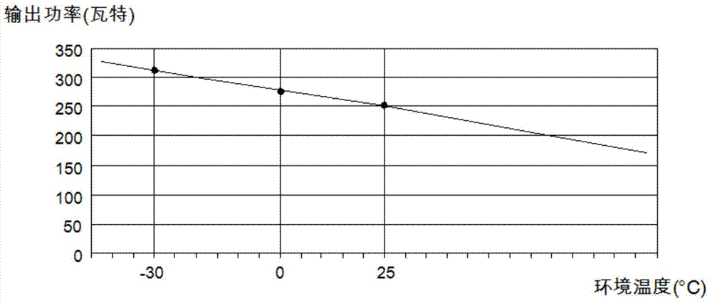
[0006] Conversely, when the solar photovoltaic module 10A and the microinverter 20A operate at an ambient temperature of 0°C, the output power Pv of the solar photovoltaic module is 280 watts, however, the rated output power of the microinverter 20A is still When the output power of the solar photovoltaic module is 250 watts, although the output power Pv of the solar photovoltaic module increases due to the decrease of the ambient temperature, it is limited by the rated output power of the micro-inverter 20A, so the micro-inverter 20A can only output 250 watts
In other words, the output power that the solar photovoltaic module 10A can generate more than the rated output power of the micro-inverter 20A cannot be effectively and fully utilized, so in this case, the utilization rate of the output power Pv of the solar photovoltaic module will be reduced. Low

Method used


Image

  • Micro inverter of solar power generation system, and operation method thereof
  • Micro inverter of solar power generation system, and operation method thereof
  • Micro inverter of solar power generation system, and operation method thereof

Examples


Embodiment Construction

[0064] In order to make the purpose, technical solutions and advantages of the embodiments of the present invention clearer, the technical solutions in the embodiments of the present invention will be clearly and completely described below in conjunction with the drawings in the embodiments of the present invention. Obviously, the described embodiments It is a part of embodiments of the present invention, but not all embodiments. Elements and features described in one drawing or one embodiment of the present invention may be combined with elements and features shown in one or more other drawings or embodiments. It should be noted that representation and description of components and processes that are not related to the present invention and known to those of ordinary skill in the art are omitted from the drawings and descriptions for the purpose of clarity. Based on the embodiments of the present invention, all other embodiments obtained by persons of ordinary skill in the ar...


PUM


Abstract

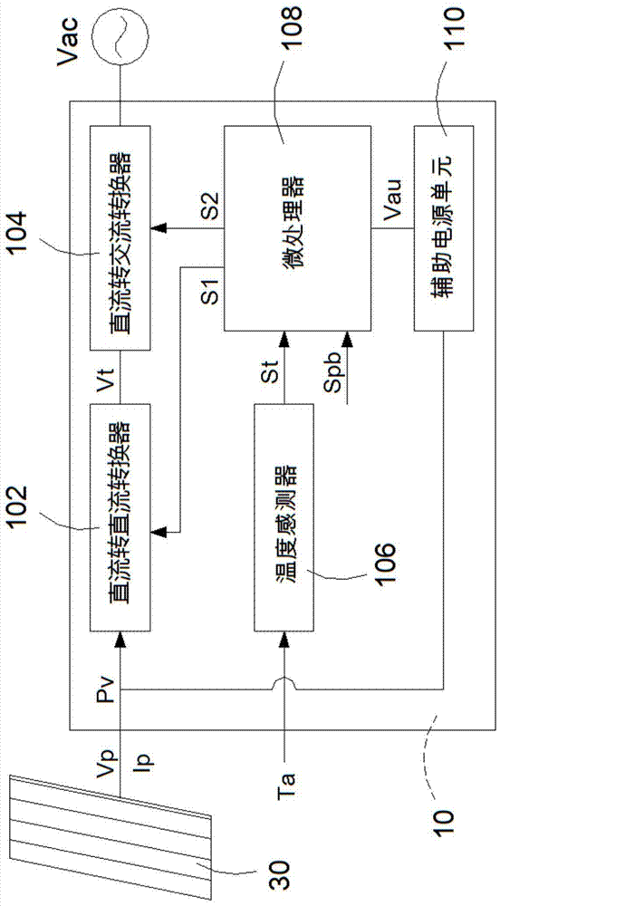
The invention discloses a micro inverter of a solar power generation system, and an operation method thereof. The method comprises the following steps: first of all, obtaining an output power value of a solar photovoltaic module, then, determining whether the micro inverter starts a power boosting mode, if the micro inverter starts the power boosting mode, boosting the maximum output power value of the micro inverter from a rated output power value to a maximum output power value, finally, determining whether the output power value of the solar photovoltaic module is greater than the maximum output power value, and if the output power value of the solar photovoltaic module is greater than the maximum output power value, the output power of the micro inverter being the maximum output power value. According to the invention, by use of the characteristic that the temperature of a solar battery itself and the maximum output power are negative temperatures, the solar photovoltaic module is enabled to output higher power when being operated in a low-temperature environment, the operation alternative of the power boosting mode is provided, the generating efficiency is improved, the generating cost is reduced, and the system application adaptability is enhanced.

Description

technical field [0001] The invention relates to a micro-inverter of a solar power generation system and an operation method thereof, in particular to a micro-inverter of a solar power generation system with a power boost operation mode and an operation method thereof. Background technique [0002] Since the two oil crises occurred in the 1970s and 1980s, the search and research of alternative energy sources has become one of the main policies of various important countries. Moreover, due to the rapid development of industrialization recently, the shortage of petrochemical energy has caused the price to rise, and another environmental problem derived is that excessive carbon dioxide emissions have caused the earth's climate to be abnormal and the temperature to rise. In order to effectively reduce the dependence on petrochemical energy, many renewable energy sources have emerged, such as solar energy and wind energy. Since solar energy is non-polluting, non-pollution-free, a...

Claims


Application Information

Patent Timeline
IPC IPC(8): H02M7/42H02S10/00
CPCY02E10/56H02M7/42H02S10/00
Inventor 李圣华
Owner DELTA ELECTRONICS INC
Learn More