Vertical machining centre machine tool

A technology of vertical machining centers and machine tools, applied in the direction of metal processing machinery parts, metal processing equipment, manufacturing tools, etc. Machine tool processing accuracy and service life and other issues, to achieve the effect of reasonable use of equipment space, guarantee protection, improve processing efficiency and processing accuracy

Inactive Publication Date: 2015-04-22
CHONGQING WNC INTELLIGENT EQUIP
View PDF6 Cites 7 Cited by
  • Summary
  • Abstract
  • Description
  • Claims
  • Application Information

AI Technical Summary

Problems solved by technology

[0002] The structure of the vertical machining center machine tool is various. The structure of the vertical machining center machine tool in the prior art mainly includes fixed column dynamic table type, moving column dynamic table type, small gantry type and other structures. These structures are in the process of processing The workpieces are all involved in feeding, so this structure has a direct or indirect impact on the acceleration performance of the machine tool; at the same time, the machine tool with this structure directly affects the speed, acceleration, accuracy and life of the machining operation; the above-mentioned vertical machining center machine tools The existing problems of the structure: 1) The workbench participates in the feed movement under the load, and the different lo

Method used


Image

  • Vertical machining centre machine tool

Examples


Embodiment Construction

[0017] In the following, with reference to the drawings, through the description of the embodiments, the specific embodiments of the present invention such as the shape and structure of the various components involved, the mutual position and connection relationship between the various parts, the function and working principle of each part, and the manufacturing process And the operation and use method, etc., are described in further detail to help those skilled in the art have a more complete, accurate and in-depth understanding of the inventive concept and technical scheme of the present invention.

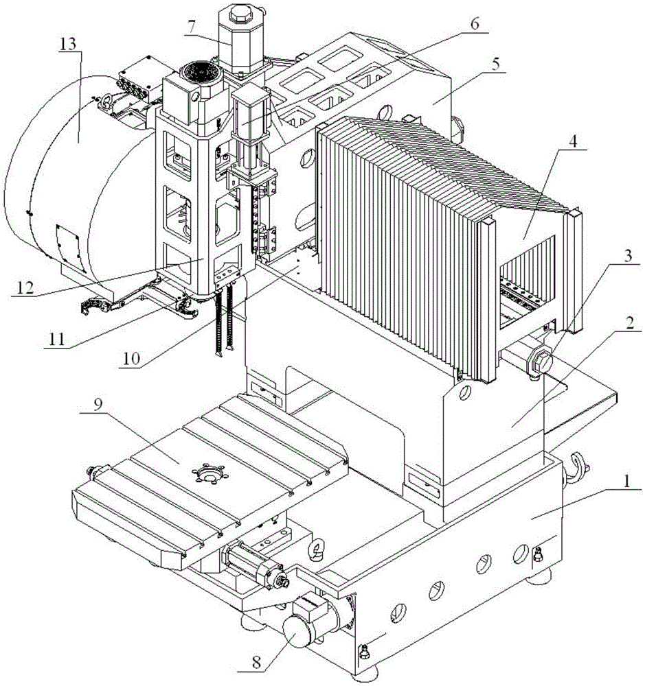
[0018] figure 1 It is a schematic diagram of a vertical machining center machine tool of the present invention; as shown in the figure, a vertical machining center machine tool of the present invention includes a base 1 horizontally placed on the ground, a bed 2 is set on the base 1, and the base 1 is placed on the bed One side of the body 2 is provided with a worktable 9 that can ...


PUM


Abstract

The invention discloses a vertical machining centre machine tool which comprises a base horizontally arranged on the ground. A lathe bed is arranged on the base, a workbench capable of doing horizontal progressive rotation is arranged on the side, on the lathe bed, of the base, a vertical column is arranged on one side of the lathe bed, a cross-shaped sliding plate horizontally arranged on the lathe bed is arranged at the connecting position of the vertical column and the lathe bed, and a spindle wrapping a spindle box is arranged on one side of the vertical column. The spindle box can vertically move along the vertical column in the Z-axis direction. The vertical column can horizontally move along the cross-shaped sliding plate in the Y-axis direction. The cross-shaped sliding plate can horizontally move along the lathe bed in the X-axis direction, and the vertical machining centre machine tool is provided with an automatic tool switching system. According to the technical scheme, the vertical machining centre machine tool can move in three-dimensional space, the automatic tool switching system achieves automatic tool switching of the machine tool, and machining efficiency and machining precision are improved. The defects that a workbench in the prior art participates in feeding motion under the condition of loads, the loads of the workbench are different, and the feeding speed and response time of the machine tool are influenced are overcome.

Description

Technical field [0001] The present invention belongs to the field of mechanical manufacturing. More specifically, the present invention relates to a vertical machining center machine tool. Background technique [0002] The structure of the vertical machining center machine tool is diverse. The structure of the vertical machining center machine tool of the prior art mainly includes a fixed column movable working table, a movable column movable working table, a small gantry type and other structures. These structures are in the process of processing. The workpieces are all involved in the feed, so this structure has a direct or indirect impact on the acceleration performance of the machine tool; at the same time, the machine tool of this structure directly affects the speed, acceleration, accuracy and life of the processing operation; the above-mentioned vertical machining center machine tools Problems with the structure of the machine: 1) The worktable participates in the feed mov...

Claims


Application Information

Patent Timeline
IPC IPC(8): B23Q1/01B23Q1/26B23Q11/00B23Q3/157B23Q11/08B23Q5/28
CPCB23Q1/01B23Q1/26B23Q3/157B23Q5/28B23Q11/00B23Q11/0042B23Q11/0825
Inventor 覃志洪张永灿黄刚强刘诗喻
Owner CHONGQING WNC INTELLIGENT EQUIP
Why Eureka
Try Eureka