Polymer melt pressure monitoring system used for micro injection molding process

A monitoring system and melt pressure technology, applied in the field of polymer melt pressure monitoring system, can solve the problems of inconvenient flow channel cleaning, small diameter of the front end of the embedded sensor, leakage, etc.

Active Publication Date: 2015-04-22
ZHEJIANG HENGDAO TECH
View PDF5 Cites 4 Cited by
  • Summary
  • Abstract
  • Description
  • Claims
  • Application Information

AI Technical Summary

Problems solved by technology

However, opening holes in the mold cavity destroys the integrity and sealing of the mold cavity, and it is easy to damage and cause leakage in a high-pressure environment
In addition, the embedded pressure sensor also has the following defects: (1) When the measured fluid is a chemical solvent, it will corrode and damage the sensor material embedded in the flow channel wall, and even chemically react with it; (2) The pressure sensor may be installed. Pockets or protrusions on the fluid flow path will affect the flow channel of the fluid, and it is not easy to clean the flow channel; (3) more critically, due to the current technical conditions, the front end of the traditional embedded sensor The diameter cannot be designed too small (for example, the minimum diameter of the melt pressure sensor currently provided by the famous sensor manufacturer Kistler is 1mm), so it cannot be applied to micro-injection molding where the flow channel size is usually only in the range of tens to hundreds of microns molding process

Method used


Image

  • Polymer melt pressure monitoring system used for micro injection molding process
  • Polymer melt pressure monitoring system used for micro injection molding process
  • Polymer melt pressure monitoring system used for micro injection molding process

Examples


Embodiment Construction

[0031] The present invention will be further described below in conjunction with the accompanying drawings and examples, but the protection scope of the present invention is not limited to the range expressed in the examples.

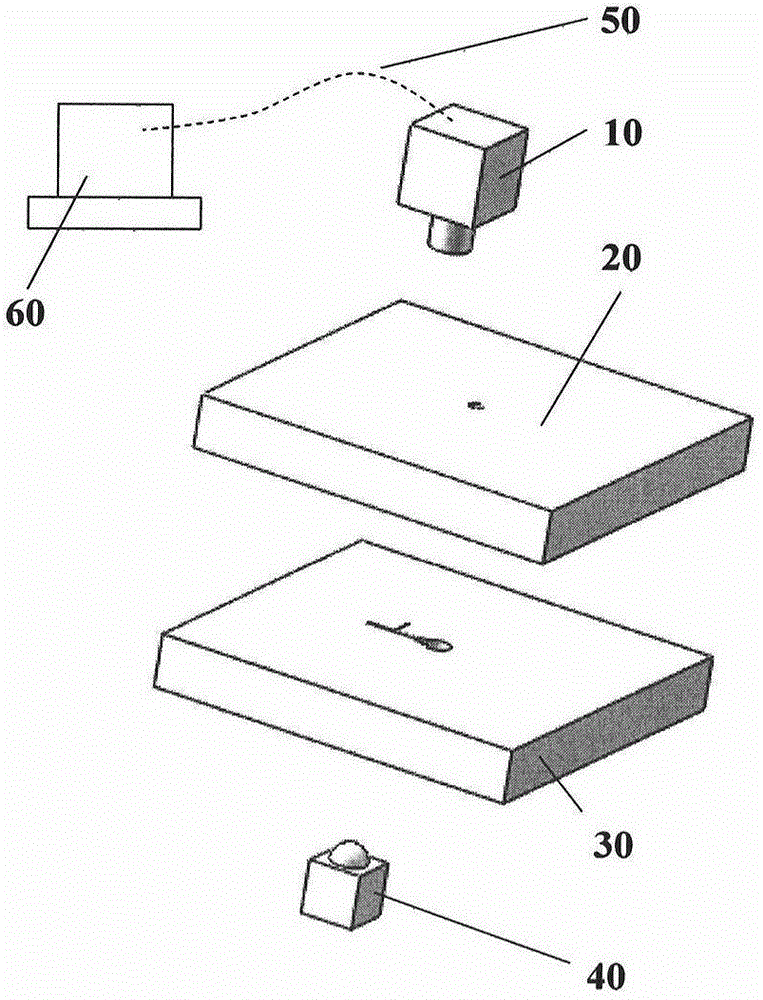
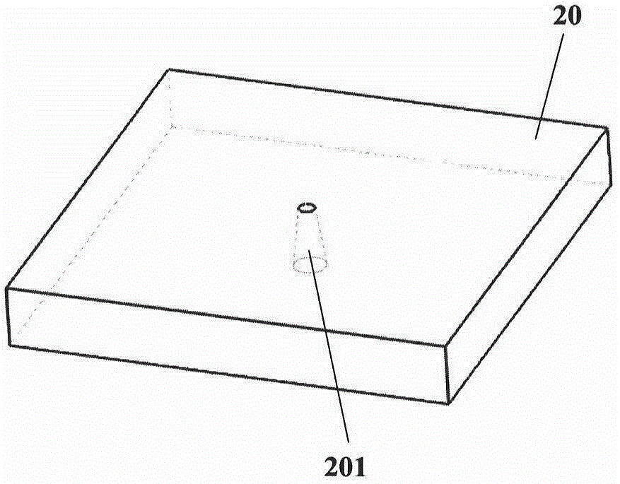
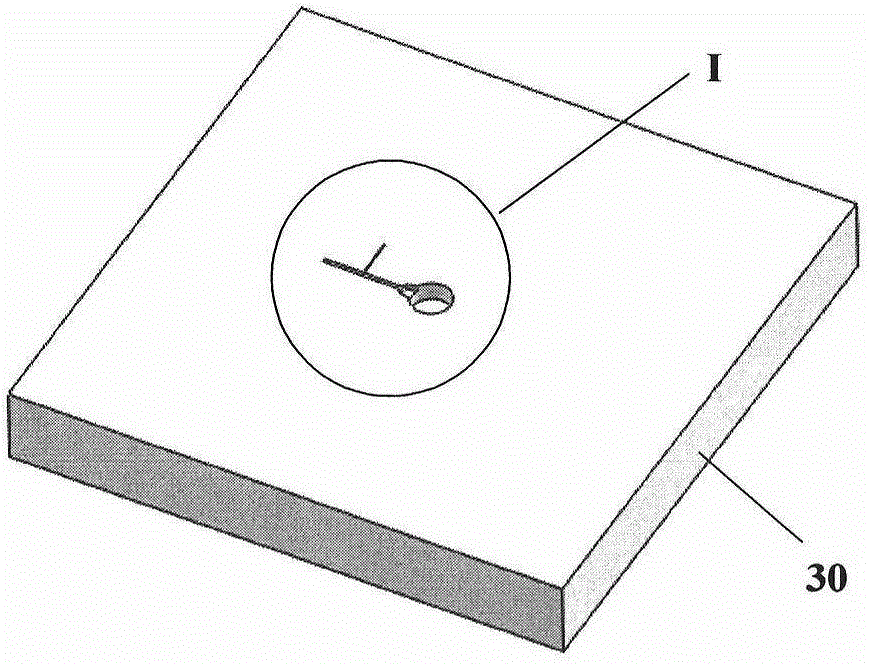
[0032] refer to Figure 1 to Figure 8 A polymer melt pressure monitoring system for micro-injection molding process provided by the present invention includes a flow module, and the flow module includes a base plate 30 and a cover plate 20 made of transparent tempered glass; one side of the base plate 30 is opened There is a material storage cavity 301, a fan gate 302, a main micro-channel 303 and an auxiliary micro-channel 304; the storage cavity 301, fan gate 302 and the main micro-channel 303 are communicated in sequence, and the auxiliary The micro-channel 304 and the main micro-channel 303 are vertical and communicated with each other, and the intersection point A of the two is a pressure monitoring point; the cover plate 20 is provided with a thro...


PUM


Abstract

The invention relates to a polymer melt pressure monitoring system used for a micro injection molding process. The polymer melt pressure monitoring system is composed of a flow module, a camera shooting module and a data processing module, wherein the flow module comprises a bottom plate and a cover plate; the bottom plate and the cover plate are made of transparent tempered glass; the bottom plate is provided with a material storage cavity, a fan-shaped gate, a main micro-channel and an assisted micro-channel; the material storage cavity, the fan-shaped gate and the main micro-channel are sequentially communicated; the assisted micro-channel and the main micro-channel are vertical to each other and are communicated; and a meeting point of the assisted micro-channel and the main micro-channel is a pressure monitoring point. When the polymer melt pressure monitoring system works, a high-speed camera of the camera shooting module records motion states of leading edges of a polymer melt in the main micro-channel and the assisted micro-channel, a time-dependent flow length function is obtained after the motion states are analyzed and processed by a computer, then a pressure curve of the polymer melt in the micro-channels is deduced through hydromechanics knowledge according to flow length of the melt and channel geometrical parameters, and the purpose of monitoring pressure of the polymer melt in injection state and pressure maintaining state in the micro injection molding process is realized.

Description

technical field [0001] The invention relates to a pressure monitoring system, in particular to a polymer melt pressure monitoring system used in a micro-injection molding process. Background technique [0002] With the rapid development of micro-electromechanical systems (MEMS), the role of polymer micro-nano molding technology, which is an important part of the field of micro-nano manufacturing, has become increasingly important. With many advantages such as low cost, high productivity, and good biocompatibility, polymer micro-nano molding technology, especially micro-injection molding technology, has been widely used in the production of many types of polymer micro-nano devices in recent years. The increasing trend of product miniaturization not only puts forward stricter requirements for the dimensional accuracy of polymer micro-nano products, but also puts forward higher requirements for its various performance indicators. As we all know, the mold cavity pressure curve ...

Claims


Application Information

Patent Timeline
Patent Type & Authority Applications(China)
IPC IPC(8): B29C45/77B29C45/27
CPCB29C45/2725B29C45/77B29C2945/76006
Inventor 杨灿尹晓红李熹平阚君武程光明
Owner ZHEJIANG HENGDAO TECH
Why Eureka
Try Eureka