
Range-increasing type electric vehicle transmission device with flywheel energy storage function

A flywheel energy storage, electric vehicle technology, applied in control devices, vehicle components, transportation and packaging, etc., can solve the problems of affecting energy saving efficiency, adverse effects on battery life, low energy recovery and utilization efficiency, etc.

Pending Publication Date: 2015-04-22
NORTHEAST FORESTRY UNIVERSITY
View PDF22 Cites 14 Cited by
  • Summary
  • Abstract
  • Description
  • Claims
  • Application Information

AI Technical Summary

Problems solved by technology

[0003] There are still some deficiencies in the above method: First, the vehicle only uses the charging method of the battery to recycle the kinetic energy in the braking process, and there are two conversions of energy forms, that is, mechanical energy-electrical energy-mechanical energy, which leads to energy loss and affects energy saving. efficiency; second, when the vehicle brakes and starts frequently, the battery is also in a state of repeated charging and discharging, which will have an adverse effect on the service life of the battery; third, when the car brakes in an emergency, the charging characteristics of the battery The limitation of electric energy recovery and storage is limited, so the efficiency of energy recovery and utilization is not high

Method used


Image

  • Range-increasing type electric vehicle transmission device with flywheel energy storage function

Examples


Embodiment Construction

[0018] The technical solutions in the embodiments of the present invention are clearly and completely described below in conjunction with the accompanying drawings.

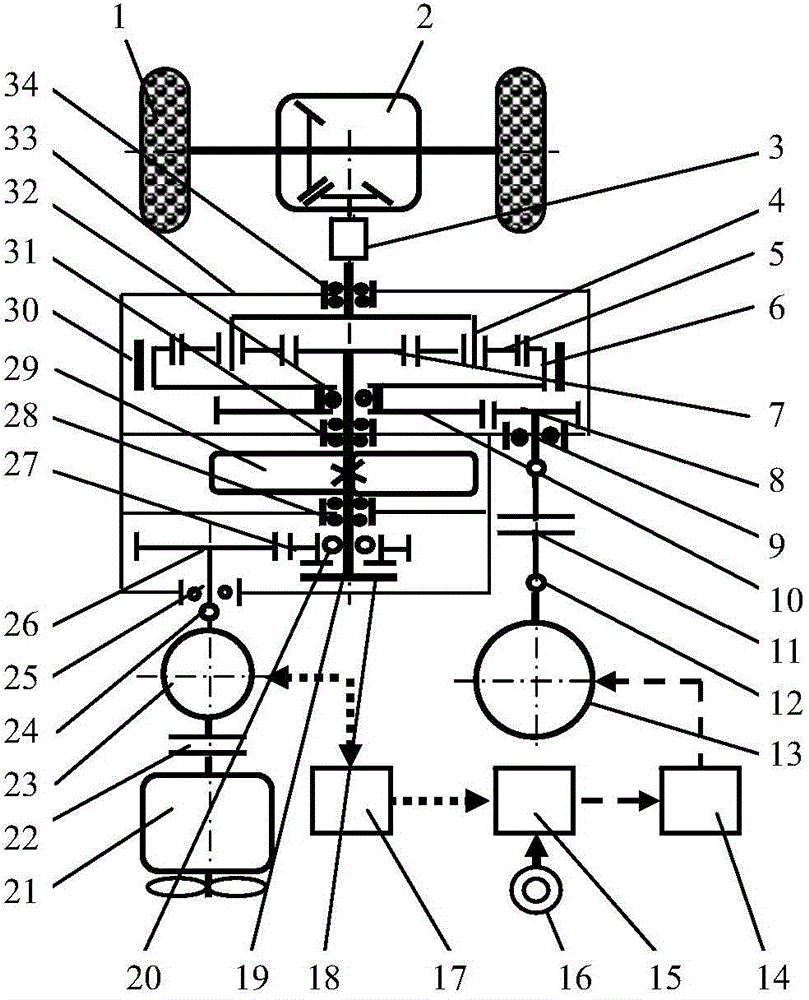
[0019] As shown in the accompanying drawings, in an extended-range electric vehicle transmission with a flywheel energy storage device according to the present invention, the planet carrier 4 is connected to the output shaft of the planetary mechanism, and the input shaft of the transmission 3 is connected to the output shaft of the planetary mechanism. , the output shaft of the transmission 3 is connected with the input shaft of the final reducer 2; the output shaft in the planetary mechanism is supported by the bearing 34 installed on the box body 33; the planetary gear 5 is installed on the planet carrier 4, and is connected with the ring gear 6 and the The sun gear 7 transmits motion in the form of gear meshing; the flywheel shaft 19 integrated with the sun gear 7 is supported by the bearing 28 and the bearing...


PUM


Abstract

The invention belongs to the field of electric vehicle engineering and relates to a range-increasing type electric vehicle transmission device with the flywheel energy storage function. The range-increasing type electric vehicle transmission device comprises a main power transmission system, a flywheel energy storage system and a vehicle-mounted charging system. The main power transmission system comprises a motor, a planet mechanism, a transmission and a main speed reducer. The flywheel energy storage system comprises a flywheel, a clutch, driven gears and a driving gear. The vehicle-mounted charging system comprises an internal combustion engine, an electric generator, a motor controller, an electric generator controller and an external charging interface. The planet mechanism comprises a sun gear, planet gears, a planet carrier, a gear ring and gear ring brakes. A flywheel is installed on a flywheel shaft. The planet carrier is connected with an output shaft of the planet mechanism. The gear ring is connected with the motor. An input shaft of the transmission is connected with the output shaft of the planet mechanism and an output shaft of the transmission is connected with an input shaft of the main speed reducer. The electric generator is connected with the internal combustion engine and the flywheel shaft. By the adoption of the range-increasing type electric vehicle transmission device with the flywheel energy storage function, the problems that an existing range-increasing type electric vehicle is low in braking energy recycling rate and the service life of a storage battery is short are solved.

Description

technical field [0001] The invention belongs to the field of electric vehicle engineering and relates to a range-extended electric vehicle transmission device with flywheel energy storage. Background technique [0002] The types of electric vehicles mainly include pure electric vehicles (Pure Electric Vehicle, PEV), hybrid electric vehicles (Hybrid Electric Vehicle, HEV) and fuel cell vehicles (Fuel Cell Electric Vehicle, FCEV). Among them, the extended-range electric vehicle is a pure electric drive electric vehicle with on-board and ground charging functions. The power system of an extended-range electric vehicle is mainly composed of a battery pack and battery management system, a main drive motor and controller, an engine and a generator system, etc. The battery pack can be charged by a ground charging pile or a vehicle charger, and the engine can be fuel-based or gas-fired. According to the operating conditions, it can operate in pure electric mode, extended range mode...

Claims


Application Information

Patent Timeline
IPC IPC(8): B60K17/26B60K17/28B60K17/04
Inventor 储江伟李洪亮詹长书陈萌崔鹏飞吴勃生张新宾王旭段超
Owner NORTHEAST FORESTRY UNIVERSITY
Learn More