Partial cable-stayed bridge with fish-back structure

A technology for part of cable-stayed bridges and fish-back beams, applied in cable-stayed bridges, bridges, bridge parts, etc., can solve problems such as unfavorable lateral planning of road engineering connections, increase the length of approach bridges, and project costs, and achieve multi-model design imagination space and landscape. Diversified design and small architectural control height

Active Publication Date: 2017-05-17
SHANGHAI URBAN CONSTR DESIGN RES INST GRP CO LTD
View PDF5 Cites 0 Cited by
  • Summary
  • Abstract
  • Description
  • Claims
  • Application Information

AI Technical Summary

Problems solved by technology

[0005] The girder height for controlling building height is higher than that of regular cable-stayed bridges with flexible stiffening girders, and the overall layout of bridges with limited requirements for building girder height (such as navigation requirements, wiring requirements, and bridge length requirements), for example, if the span needs to be increased , the girder height of the bridge must be increased first, which will inevitably increase the length of the approach bridge and the corresponding project cost, etc., and is unfavorable for the connection with the horizontal planning road project

Method used


Image

  • Partial cable-stayed bridge with fish-back structure
  • Partial cable-stayed bridge with fish-back structure
  • Partial cable-stayed bridge with fish-back structure

Examples


Embodiment 1

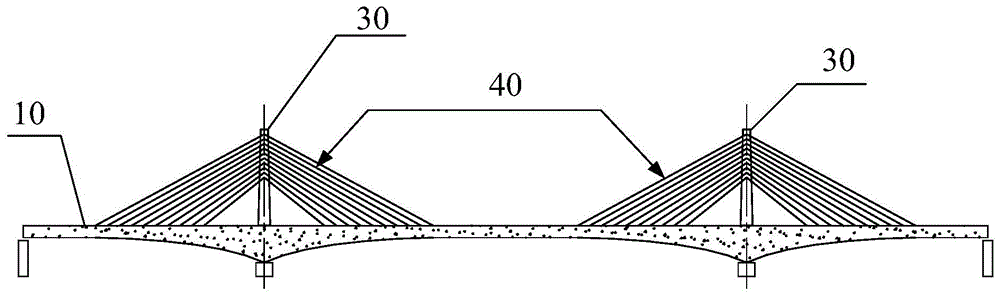
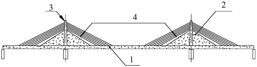
[0053] The purpose of the present invention is achieved through the following technical solutions: as figure 2 As shown, the partial cable-stayed bridge with fish-back structure provided in this embodiment is a partial cable-stayed bridge with double-tower and three-span fish-back structure, which includes: a main girder 1, several anchor ends or saddle areas erected on the The pylons 3 on the main girder 1, some vertical walls corresponding to the number of the pylons 3 one-to-one, and some stay cables 4 arranged between the main girder and the pylons, in this embodiment The vertical wall is a fish ridge wall 2, the main girder 1 is a box-type bridge deck of equal height, the columns of each of the bridge towers 3 are vertically embedded in the corresponding fish ridge wall, and each of the The top of the column of the bridge tower 3 protrudes from the fish ridge wall, one end of each stay cable 4 is stretched and anchored to the main girder 1, and the other end of each stay...

Embodiment 2

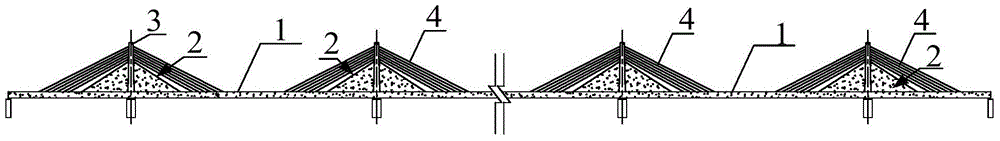
[0076] According to the needs of actual engineering and stress, this embodiment provides a partial cable-stayed bridge with multi-tower and multi-span fish-back structure.

[0077] image 3 It is a structural diagram of the facade direction of a partial cable-stayed bridge with multi-tower and multi-span fish-back structure.

[0078] Such as image 3 As shown, the number of pylons 3 of the partial cable-stayed bridge in this embodiment is multiple, and the number of spans of the partial cable-stayed bridge is multiple.

[0079] The structure of fish ridge wall 2, bridge tower 3, main girder 1 in this embodiment, and the connection mode of stay cable 4 and bridge tower 3, main girder 1 are all identical with embodiment 1.

Embodiment 3

[0081] According to the needs of actual engineering and stress, the fish ridge wall of part of the cable-stayed bridge in this embodiment is a single piece of fish ridge wall.

[0082] Figure 4a It is the layout structure diagram of the monolithic fish ridge wall and bridge tower in the direction of cross section. Such as Figure 4a As shown, the single fishbone wall is arranged in the middle of the cross section of the main beam 1 .

[0083] The structure of fish ridge wall 2, bridge tower 3, main girder 1 in this embodiment, and the connection mode of stay cable 4 and bridge tower 3, main girder 1 are all identical with embodiment 1.


PUM


Abstract

The invention discloses a partial cable-stayed bridge of a fish bone beam structure. The partial cable-stayed bridge of the fish bone beam structure comprises a main beam, a plurality of bridge towers and stayed cables, wherein anchoring ends or saddle areas of the bridge towers are arranged on the main beam, the stayed cables are arranged between the main beams and the bridge towers, part of stayed cables further comprise multiple vertical walls corresponding to the bridge towers one to one, the vertical walls are fish bone walls, the main beam is an equal-altitude box type bridge panel, columns of the bridge towers are embedded in the corresponding fish bone walls, and the tops of the columns of the bridge towers extend out of the fish bone walls. One end of each stayed cable is tensioned and anchored on the main beam, and the other ends of the stayed cables are anchored at the tops of the bridge towers or continuously pass through the saddle areas. The partial cable-stayed bridge of the fish bone beam structure has all the advantages of a traditional cable-stayed bridge. The structural rigidity of a bridge body is high, the stress of the bridge towers is more reasonable, the fish bone walls have the function of the bridge towers, the section is larger, and the bending performance is better.

Description

technical field [0001] The invention relates to a cable-stayed bridge, in particular to a partial cable-stayed bridge with a fish spine structure. Background technique [0002] The partial cable-stayed bridge is a transitional bridge between the cable-stayed bridge with very flexible stiffened girders and the girder bridge with very high girder height. The tower is shorter. This bridge type has the dual characteristics of cable-stayed bridge and girder bridge, so it is called "partial cable-stayed bridge". It is related to the ratio of the stiffness of the stay cables to the stiffness of the stiffening beam. [0003] Generally speaking, the continuous beam bears the vertical load by bending and shearing, the cable-stayed bridge bears the vertical load by the compression of the beam and the tension of the cable, and some cable-stayed bridges adopt the form of cables, Such as figure 1 As shown, in a part of the cable-stayed bridge, the external prestressed tendons are move...

Claims


Application Information

Patent Timeline
Patent Type & Authority Patents(China)
IPC IPC(8): E01D11/04E01D19/14
CPCE01D11/04E01D19/14
Inventor 陆元春傅梅赵成栋侯引程
Owner SHANGHAI URBAN CONSTR DESIGN RES INST GRP CO LTD
Why Eureka
Try Eureka