A high-power ultra-short laser pulse contrast measurement device

A technology of ultra-short lasers and measuring devices, which is applied in the direction of instruments, etc., can solve the problems of narrow dynamic range and low pulse utilization rate, achieve high dynamic range, increase the length of recording time, and improve the effect of detectability

Inactive Publication Date: 2017-08-15
LASER FUSION RES CENT CHINA ACAD OF ENG PHYSICS
View PDF3 Cites 0 Cited by
  • Summary
  • Abstract
  • Description
  • Claims
  • Application Information

AI Technical Summary

Problems solved by technology

[0003] In order to overcome the shortcoming of narrow dynamic range caused by low pulse utilization rate in the ultrashort laser pulse contrast measurement of the measuring device in the prior art, the present invention provides a high-power ultrashort laser pulse contrast measurement device

Method used


Image

  • A high-power ultra-short laser pulse contrast measurement device

Examples


Embodiment 1

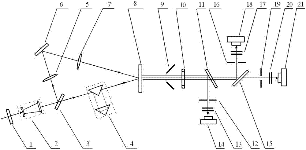
[0019] figure 1 It is a schematic diagram of the optical path of the high-power ultrashort laser pulse contrast measurement device of the present invention. figure 1 In the high-power ultrashort laser pulse contrast measurement device of the present invention, the half-wave plate 1, the beam expander 2, and the beam splitter I3 are sequentially arranged in the incident direction of the high power ultrashort laser pulse. The incident pulse light enters the half-wave plate 1, the beam expander 2, the beam splitter I3 in turn, and is divided into the transmitted light and the reflected light by the beam splitter I3. A delay adjuster 4 is set on the transmission light path of the beam splitter I3. A convex lens I5, a limiter 6, and a convex lens II 7 are sequentially arranged on the reflection light path of the beam mirror I3. The reflected light of the beam splitter I3 is condensed to the limiter 6 by the convex lens I3, and the light reflected from the limiter 6 becomes parallel...


PUM


Abstract

The invention provides a high-power ultrashort laser pulse contrast measuring device. In the measuring device, a half-wave plate, a beam expander, and a beam splitter I are sequentially arranged in the incident direction of the high-power laser pulse, and a delay adjuster is arranged on the transmitted light path of the beam splitter I. Convex lens I, limiter, and convex lens II are arranged in turn on the reflected light path; the parallel light emitted from the delay adjuster and the parallel light emitted from convex lens II enter the sum frequency crystal in parallel, and the frequency doubled light generated by the sum frequency crystal is converged by the cylindrical convex lens , the converging light is divided into left, middle and right paths by beam splitter II and beam splitter III along the horizontal direction, and enters the respective photodetectors for collection after different attenuation to obtain contrast information. The invention has high sensitivity and wide testing dynamic range.

Description

Technical field [0001] The invention belongs to the technical field of ultrashort laser pulse testing, and specifically relates to a high-power ultrashort laser pulse contrast measurement device. Background technique [0002] In the process of the interaction between the ultrashort laser pulse and the substance, if the intensity of the focused pre-pulse reaches a certain value, plasma will be generated, which will prevent the transmission of the subsequent main pulse, which will seriously affect the analysis of the experimental results. The pulse contrast becomes a restriction on physical experiments and The main bottleneck of laser device performance improvement. At present, the contrast measurement of ultrashort pulse mainly adopts the third-order correlation method. The Chinese utility model patent (patent number: ZL200720077677.0) named "High-power ultrashort laser pulse contrast measurement device" discloses a pulse contrast measurement method that obtains third-order corre...

Claims


Application Information

Patent Timeline
Patent Type & Authority Patents(China)
IPC IPC(8): G01J11/00
Inventor 夏彦文刘华孙志红董军彭志涛朱启华粟敬钦
Owner LASER FUSION RES CENT CHINA ACAD OF ENG PHYSICS
Why Eureka
Try Eureka