
Cryogenic liquid cavitation experimental device

An experimental device and cryogenic liquid technology, applied in measuring devices, fluid dynamics tests, instruments, etc., can solve problems that affect the effect of cavitation experiments, poor heat insulation, and large footprint

Inactive Publication Date: 2015-04-22
BEIJING INSTITUTE OF TECHNOLOGYGY
View PDF4 Cites 28 Cited by
  • Summary
  • Abstract
  • Description
  • Claims
  • Application Information

AI Technical Summary

Problems solved by technology

[0004] The cryogenic liquid cavitation experimental device improved on the basis of the traditional cavitation experimental device requires large-scale equipment such as an annular water tunnel, and a high-power cryogenic pump to realize liquid circulation. There are many experimental equipment and other auxiliary devices, and often only packaged insulation can be used. Thermal materials approach prevents endothermic phase transitions of cryogenic liquids
Such experimental equipment has the following disadvantages: 1. It occupies a large area, has a large investment cost, and high use and maintenance costs; 2. The experimental equipment and structure are complicated. If other types of experiments are required, it is inconvenient to replace the test section, and it is difficult Replace the flow medium; 3. Poor heat insulation makes it difficult to achieve visual observation, which affects the effect of cavitation experiments. 4. The dynamic adjustment ability of the experimental device is poor and cannot be moved. 5. The safety is poor. It is very easy to cause harm to experimenters; 6. The consumption of cryogenic liquid is large during use, resulting in more waste of resources, noise and waste pollution

Method used


Image

  • Cryogenic liquid cavitation experimental device
  • Cryogenic liquid cavitation experimental device
  • Cryogenic liquid cavitation experimental device

Examples


Embodiment 1

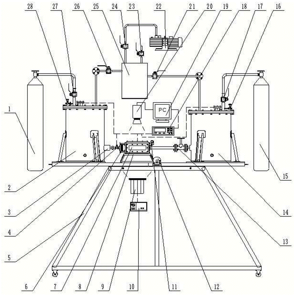
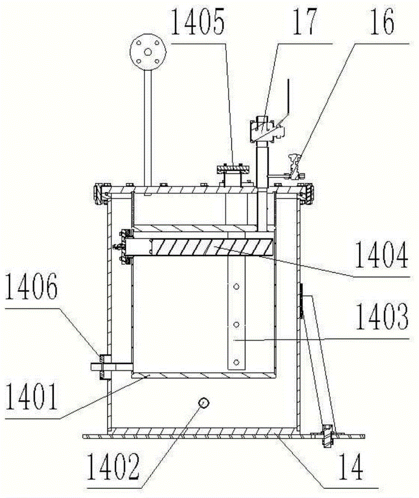
[0046] A low-temperature liquid cavitation experiment device is generally divided into five parts: a supply tank part, a test section part, a collection tank part, a pressure regulating tank part, and an auxiliary equipment part.

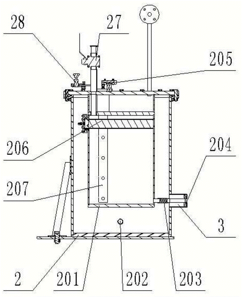
[0047] Supply tank parts such as figure 2As shown, it is used to store and provide cryogenic liquid, and the pressure and temperature of cryogenic liquid can be adjusted; it includes supply tank outer cover 2, supply tank liner 201, supply tank vacuum interface 202, filter joint 203, filter 3, supply tank Tank sealing ring 204, supply tank sensor interface 205, supply tank pressurization valve 27, supply tank pressure relief valve 28, supply tank horizontal level gauge 206, supply tank vertical level gauge 207, connection relationship: supply tank cover 2 upper welding There are 3 brackets, the supply tank bracket and the experimental device bracket 5 are connected by bolts, and the supply tank is fixed on the experimental device bracket 5; the sup...


PUM


Abstract

The invention belongs to the technical fields of fluid machinery engineering, cryogenic engineering and aerospace engineering and relates to cavitation experimental devices, in particular to a cryogenic liquid cavitation experimental device. The cryogenic liquid cavitation experimental device comprises a testing segment part, a pressure-regulating tank part and an auxiliary device part. Different from a traditional cavitation experimental device, the cryogenic liquid cavitation experimental device is characterized in that pressure and temperature adjustment is performed on the experimented cryogenic liquid through pressure control, and flowing adjustment is performed through pressure difference between a supply tank part and a collection tank part. The device can achieve synchronous collection of images, pressure data, temperature data and flow data of a cryogenic liquid cavitation flow field, and is good in experiment effect and high in safety; in addition, experiment equipment is easy and portable, convenient to disassemble and carry, small in occupied space and capable of saving experiment area.

Description

technical field [0001] The invention relates to a cavitation experiment device, in particular to a low-temperature liquid cavitation experiment device. It belongs to the technical fields of fluid mechanical engineering, cryogenic engineering and aerospace engineering. Background technique [0002] When the internal partial pressure of the liquid at a certain temperature is reduced to the saturated vapor pressure of the liquid, vaporization will occur, and the gas dissolved in the liquid will also precipitate out to form bubbles (also known as voids, cavities). After the flow moves to a place of higher pressure, the vapor in the bubble recondenses and the bubble collapses. The process of the generation, development, and collapse of cavitation in this liquid flow, as well as the resulting series of physical and chemical changes, are called cavitation. The occurrence of cavitation often leads to a decrease in machine efficiency and causes problems such as vibration, noise, an...

Claims


Application Information

Patent Timeline
IPC IPC(8): G01M10/00
Inventor 王国玉陈泰然张敏弟黄彪齐海阔李达钦
Owner BEIJING INSTITUTE OF TECHNOLOGYGY
Learn More