Polarization error restraining device and method for Y waveguide loop of optical current transformer

A fiber optic current and error suppression technology, applied in the direction of voltage/current isolation, etc., can solve the polarization characteristics of Y waveguide loop of fiber optic current transformer and its suppression technology, which affects the stability of transformer measurement accuracy and transformer measurement accuracy Larger impact and other problems, to achieve the effect of improving the measurement accuracy of small currents, improving stability, and reducing optical path loss

Active Publication Date: 2015-04-22
胡雨亭
View PDF7 Cites 3 Cited by
  • Summary
  • Abstract
  • Description
  • Claims
  • Application Information

AI Technical Summary

Problems solved by technology

The reason is: the Y-waveguide loop formed by the Y-waveguide phase modulator and the coupler input pigtail can be equivalent to an M-Z interferometer or a Sagnac interferometer, which is sensitive to vibration and rotation effects and affects the stability of the measurement accuracy of the transformer
[0014] b) The polarization error of the Y waveguide loop has a great influence on the measurement accuracy of the transformer
[0015] At present, there is no research on the polarization characteristics and suppression technology of the Y-waveguide loop of the fiber optic current transformer

Method used


Image

  • Polarization error restraining device and method for Y waveguide loop of optical current transformer
  • Polarization error restraining device and method for Y waveguide loop of optical current transformer
  • Polarization error restraining device and method for Y waveguide loop of optical current transformer

Examples


Embodiment Construction

[0024] The technical solutions of the present invention will be further described in detail below in conjunction with the accompanying drawings and embodiments.

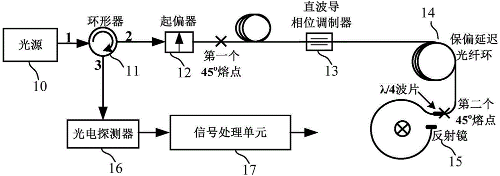
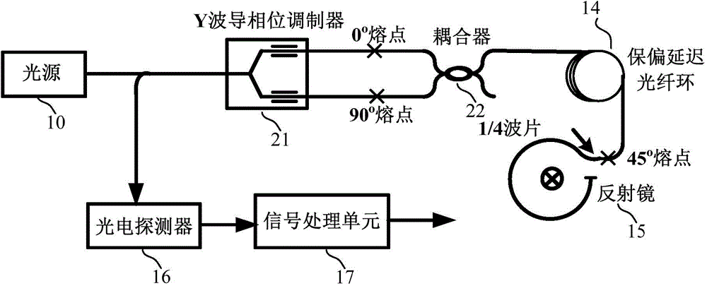
[0025] The present invention adopts the combination of Y waveguide phase modulator and polarization beam splitter to replace figure 2 The combination of the Y waveguide phase modulator and the coupler in the paper can effectively suppress the polarization error introduced by the waveguide loop as a new type of optical path design by asymmetrically matching the arm length difference between the two arms of the Y waveguide loop.

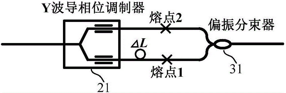
[0026] The invention provides a polarization error suppressing device of a Y waveguide loop of an optical fiber current transformer, such as image 3 As shown, it includes a Y waveguide phase modulator 21 and a polarization beam splitter 31. The two output pigtails of the Y waveguide phase modulator 21 are connected to the two input pigtails of the polarization beam splitter 31 through melti...


PUM


Abstract

The invention provides a polarization error restraining device and method for a Y waveguide loop of an optical current transformer, and belongs to the field of optical sensing technologies. The Y waveguide loop is formed by a Y waveguide phase modulator and a polarization beam splitter. Two output tail fibers of the Y waveguide phase modulator are connected with two input tail fibers of the polarization beam splitter through a fusion point (1) and a fusion point (2) respectively. The two tail fibers connected through the fusion point (1) and the two tail fibers connected through the fusion point (2) form two arms of the Y waveguide loop respectively, the two arms of the Y waveguide loop are not equal in length, and the length difference of the arms is delta L. The input tail fiber of the Y waveguide phase modulator is connected with a circulator, and the output tail fiber of the polarization beam splitter is annularly connected with a polarization-maintaining delay optical fiber. Optical path losses can be further reduced, the shot noise of a detector is lowered, and the small current measurement precision of the transformer is improved. Through restraining the polarization errors of the Y waveguide loop, the stability of the small current measurement precision can be further improved.

Description

technical field [0001] The invention relates to a polarization error suppression device and method for a Y waveguide loop of an optical fiber current transformer, and belongs to the technical field of optical fiber sensing. Background technique [0002] The all-fiber optic current transformer based on the Faraday effect is recognized as a substitute for the traditional electromagnetic induction current transformer due to its principle advantages. Under the background of the country's vigorous development of UHV and smart grids, optical fiber current transformers, as a symbolic component of smart grids, have been equipped and applied on a small scale. Constrained by factors such as optical path noise and digital quantization noise, the accuracy and stability of small current measurement It is difficult to meet the needs of metrology applications, which has become the main technical bottleneck restricting its application in the field of metrology equipment. [0003] The mains...

Claims


Application Information

Patent Timeline
Patent Type & Authority Applications(China)
IPC IPC(8): G01R15/24
Inventor 胡雨亭
Owner 胡雨亭
Why Eureka
Try Eureka