Supercharge Your Innovation With Domain-Expert AI Agents!

Optical switch

An optical switch and optical fiber technology, applied in the field of optical switches, can solve the problems of extremely high manufacturing process requirements, expensive devices, and slow speed of micro-electromechanical array switches, and achieve integration, fast switching speed, and low insertion loss. Effect

Inactive Publication Date: 2015-04-22
梁联长
View PDF6 Cites 8 Cited by
  • Summary
  • Abstract
  • Description
  • Claims
  • Application Information

AI Technical Summary

Problems solved by technology

The manufacturing process of MEMS array switches is extremely demanding, and the device is expensive; magneto-optical switches and liquid crystal switches also have the problem of slow speed (0.1-1ms level)

Method used


Image

  • Optical switch
  • Optical switch
  • Optical switch

Examples


Embodiment

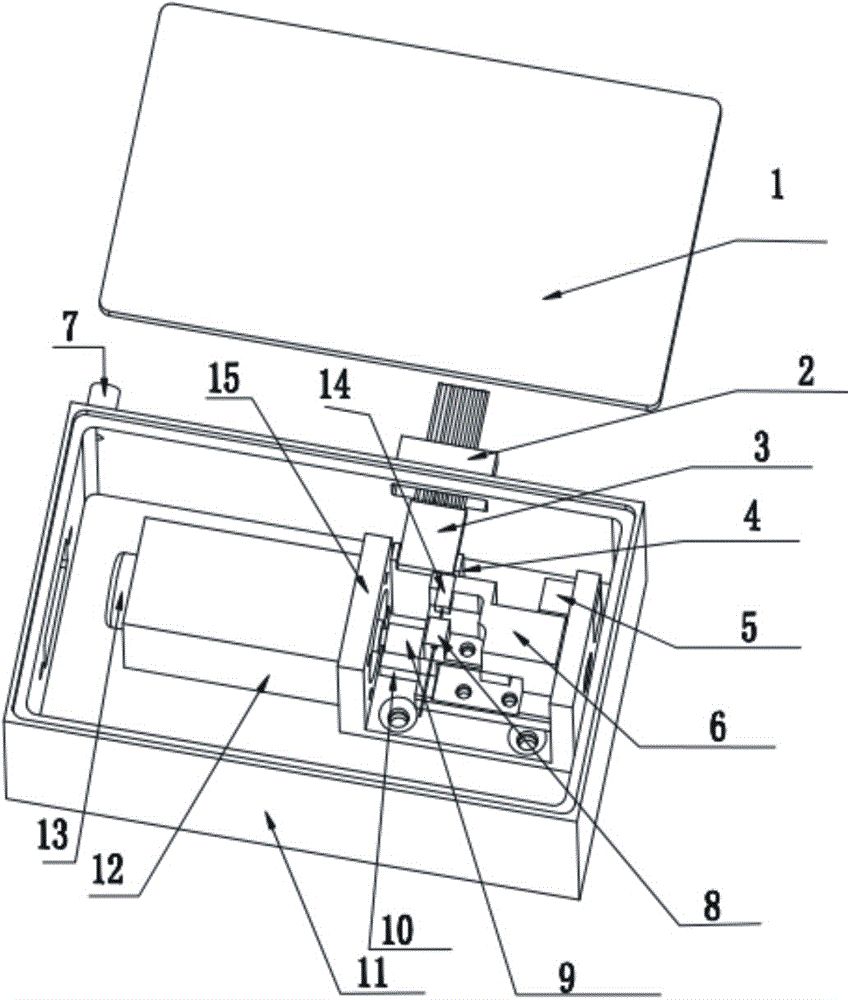
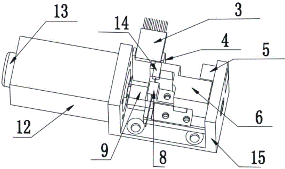
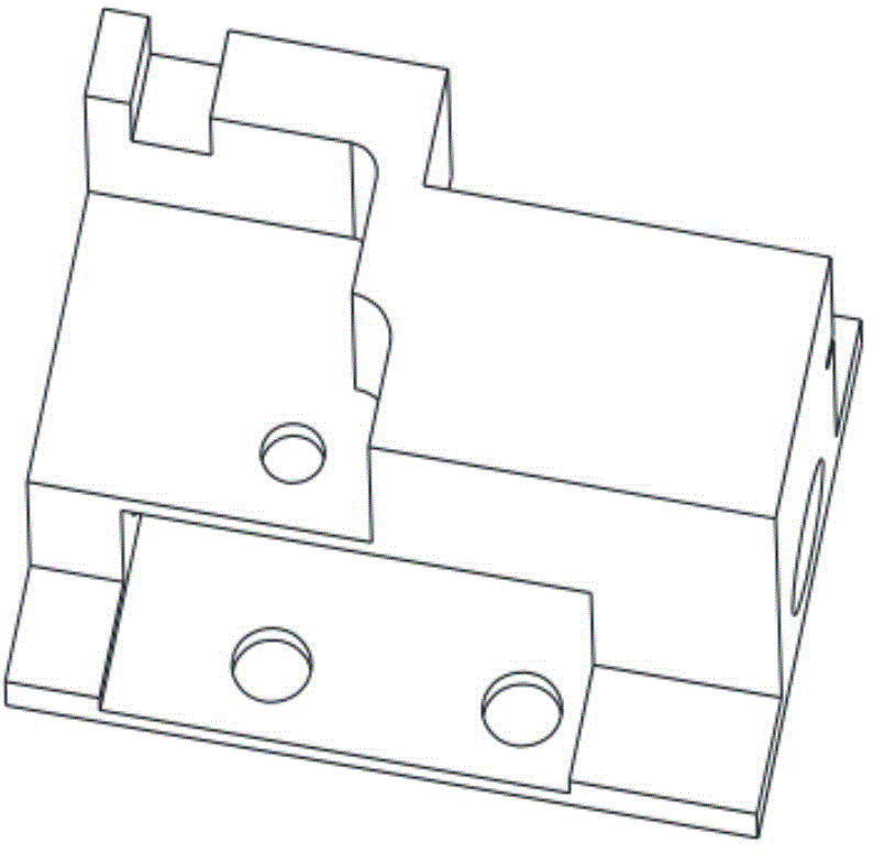
[0019] An optical switch, comprising a box body 11 and a box cover 1, a cavity is provided in the box body 11, an optical fiber inlet 7 and an optical fiber output port 2 are provided on the box body 11, and the optical fiber output port is a multi-fiber array 3, The multi-fiber array 3 is fixed on the box body 11 through the fiber array bracket 4, and the box body 11 has an adjustment device for switching optical paths. The adjusting device includes a motor 12, a U-shaped block 15, a guide rail 10, a slide block 6, a screw mandrel 9 and a photoelectric sensor 5. The cross-section of the U-shaped block 15 is a U-shaped structure, and the bottom of the U-shaped block 15 is installed on the box body The inner bottom of 11, motor 12 is installed on one side of U-shaped block 15, the output end of motor 12 connects screw mandrel 9 and drives screw mandrel 9 to rotate, guide rail 10 is positioned at the inner bottom of U-shaped block 15, guide rail 10 and screw mandrel 9 Arrang...


PUM


Abstract

The invention belongs to the field of optical switches, and relates to an electric mechanical type optical switch for overcoming various defects existing in an existing optical switch. The optical switch comprises a box and a box cover. The box is provided with an optical fiber access port and a multi-optical fiber array optical fiber output port. The box is internally provided with an adjusting device switching an optical path. The adjusting device comprises a motor, a U-shaped block, a guide rail, a sliding block, a lead screw and a photoelectric sensor. The bottom of the U-shaped block is installed at the bottom in the box, the motor is installed at one side of the U-shaped block, the output end of the motor is connected with the lead screw and drives the lead screw to rotate, the sliding block is arranged on the guide rail, the lead screw penetrates through the sliding block, the sliding block is provided with an optical fiber fixing support used for fixing a single optical fiber array, and the optical fiber fixing support is provided with the single optical fiber array. The motor servo controls the parallel movement of the input light, an input lens optical fiber is shifted through the rotation of the motor servo, and therefore the optical path switching is achieved. Thus, the optical switch is simple in structure, low in cost, reliable in performance and easy to achieve.

Description

technical field [0001] The invention belongs to the field of optical switches, in particular to an optical switch in which a single optical fiber is connected to a plurality of optical fiber arrays. Background technique [0002] With the rapid development of communication and information network technology, people have higher and higher requirements for capacity, communication speed, etc., and traditional electronic communication has been difficult to meet the requirements. A brand-new optical fiber communication technology emerging at present—optical crossover interconnection technology will fundamentally solve the electronic bottleneck problem, thereby realizing all-optical communication. Optical switches are key components in optical cross-connect and dense wavelength division multiplexing (DWDM) systems. The optical switch cooperates with the dense wavelength division multiplexer to realize free routing of each wavelength and realize all-optical switching. In recen...

Claims


Application Information

Patent Timeline
IPC IPC(8): G02B6/35
CPCG02B6/3508
Inventor 梁联长
Owner 梁联长
Features
  • R&D
  • Intellectual Property
  • Life Sciences
  • Materials
  • Tech Scout
  • Unparalleled Data Quality
  • Higher Quality Content
  • 60% Fewer Hallucinations
Learn More