FPGA-based dynamic motion decoding trigger

A trigger and starting signal technology, applied in the direction of instruments, simulators, computer control, etc., can solve the problems of difficult to achieve the accuracy requirement of the acquisition cycle, the mismatch between the beginning and the end of the experimental data, and the inability to process the experimental data, etc., to achieve performance improvement and high efficiency , good stability

Active Publication Date: 2015-04-22
中国航空工业空气动力研究院
View PDF8 Cites 4 Cited by
  • Summary
  • Abstract
  • Description
  • Claims
  • Application Information

AI Technical Summary

Problems solved by technology

At present, the common acquisition method is that the acquisition system uses its own clock as the reference, and collects aerodynamic data at the frequency required by the experiment. For example, the model movement frequency is 1Hz, and it is required to collect 240 sets of data per cycle. In this way, the acquisition cycle of the acquisition system should be set to 1 / 240s. Most of the systems run on the Windows platform, and the acquisition period with high precision requirements is difficult to achieve. For the situation where it is desired to collect multi-period data, the experimental data will not correspond to the beginning and the end, resulting in the inability to process the experimental data. In addition, the aerodynamic data needs to be consistent with the model position Synchronous acquisition, the common acquisition system collects the aerodynamic data and the position signal output by the control system at the same time, it is difficult to ensure synchronization

Method used


Image

  • FPGA-based dynamic motion decoding trigger

Examples


Embodiment 1

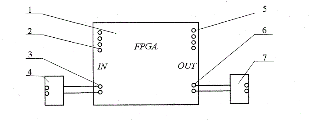
[0010] according to figure 1 As shown, a dynamic motion decoding trigger based on FPGA includes FPGA module 1, input signal level conversion circuit 4, DA circuit and pulse optocoupler conversion circuit 7, and the start of input signal level conversion circuit 4 and FPGA module 1 The signal input terminal 3 is connected, the pulse signal output terminal 6 of the FPGA module 1 is connected to the pulse optocoupler conversion circuit 7, the pulse optocoupler conversion circuit 7 is connected to the acquisition trigger terminal of the acquisition system, and the position signal output terminal 5 of the FPGA module 1 is connected to the DA The circuit is connected, the DA circuit is connected with the acquisition system, the external control system inputs the starting signal, and the input signal level conversion circuit 4 converts it into the identification voltage of the FPGA module 1; the position signal of the model is input to the encoder signal of the FPGA module 1 through t...

Embodiment 2

[0012] During the wind tunnel experiment, the encoder of the motion system is connected to the encoder signal input terminal 2, the "initial acquisition signal" output by the motion system is connected to the input signal level conversion circuit 4, and the position signal output terminal 5 of the decoding trigger It is connected to the position acquisition channel of the acquisition system, and the pulse optocoupler conversion circuit 7 of the decoding trigger is connected to the acquisition trigger end of the acquisition system. After the above connection is completed, the experiment is carried out.

[0013] For example, if the movement period of the model is 1s, it is required to collect 240 points every week for 22 weeks, and collect regularly. The following settings can be made:

[0014] The inventive device sets the model motion frequency to 1 Hz, collects 240 points every week, and the number of collection points is 22×240=5280 points. After the motion system starts to m...

Embodiment 3

[0017] The following describes the application of the system to the static motion system of the wind tunnel experiment.

[0018] The static motion system experiment requires the model to be in place, and the acquisition system collects multiple sets of experimental data and then averages them. The acquisition settings for this device are as follows

[0019] The invention equipment sets the model movement frequency to 1Hz, collects 1000 points every week, and collects 1000 points. In this way, after the model is in place, it collects 1s and collects 1000 points in total. After the data is collected by the collection system, it performs mean value processing. Every time the model reaches a position, it outputs a pulse signal to the inventive device, so that the data collection of the whole static experiment is completed.

[0020] The core technology platform of the device of the present invention is an FPGA module, i.e. a Field Programmable Gate Array (FPGA). The module includes...


PUM


Abstract

The invention relates to an FPGA-based dynamic motion decoding trigger for connecting a control system and an acquisition system. The FPGA-based dynamic motion decoding trigger is composed of an FPGA module, an input signal level conversion circuit, a DA circuit and a pulse optical coupler conversion circuit. In the experiment, a position signal of a model is inputted into the FPGA module; the FPGA module parses the position information of the model according to a designed logic program; and the information is outputted to the acquisition system by the DA circuit in an analog quantity mode. And the FPGA module outputs a pulse signal with a certain frequency or at a fixed position according to the experiment requirement; and the signal uses a model moving position set in advance as the starting point to collect a determination signal. The pulse signal is outputted to the acquisition system; and the acquisition system uses the signal as an external interrupt signal and collects aerodynamic data and model position data synchronously. The trigger has advantages of high data accuracy, high multiplicity and efficiency, and good stability.

Description

technical field [0001] The invention relates to an FPGA-based dynamic motion decoding trigger. Background technique [0002] Dynamic experiments are an important part of wind tunnel experiments. Compared with conventional static experiments, dynamic experiments can obtain experimental data that cannot be obtained by static experiments, such as dynamic derivative experiments, large-scale oscillation experiments, and rotating balance experiments. In the dynamic experiment, it is necessary to obtain the aerodynamic data during the movement of the model, and the data density is high, and the data must match the position of the movement of the model, that is, it is collected synchronously. At present, the common acquisition method is that the acquisition system uses its own clock as the reference, and collects aerodynamic data at the frequency required by the experiment. For example, the model movement frequency is 1Hz, and it is required to collect 240 sets of data per cycle. In...

Claims


Application Information

Patent Timeline
Patent Type & Authority Applications(China)
IPC IPC(8): G05B19/042
CPCG05B19/042
Inventor 王建锋刘春明王瑶黄丽婧李立
Owner 中国航空工业空气动力研究院
Why Eureka
Try Eureka