
Position control method based on fiber-optic gyroscope integral means

A fiber optic gyroscope and control method technology, applied in the field of optical aiming and position control, can solve the problems of detail and complexity, and achieve the effect of cost saving

Inactive Publication Date: 2015-04-22
西安应用光学研究所
View PDF8 Cites 3 Cited by
  • Summary
  • Abstract
  • Description
  • Claims
  • Application Information

AI Technical Summary

Problems solved by technology

However, for the output signal of the gyroscope, the principle of converting the speed signal into an angle signal is relatively simple, but in actual work, due to the existence of zero drift and zero bias in the gyroscope, the link of actually realizing the gyroscope angle integration is more detailed and complicated, and needs to be further studied Gyro signal for further processing

Method used


Image

  • Position control method based on fiber-optic gyroscope integral means
  • Position control method based on fiber-optic gyroscope integral means
  • Position control method based on fiber-optic gyroscope integral means

Examples


Embodiment Construction

[0027] Describe the present invention below in conjunction with specific embodiment:

[0028] The position control method of the optical fiber gyro integration means in the preferred embodiment of the present invention is used in the servo control system of the photoelectric stabilization system.

[0029] The servo control system of the photoelectric stabilized aiming system forms a servo control loop through gyro feedback to isolate the disturbance caused by the outside world to ensure the stability of the target aiming line; at the same time, it accepts the position deviation command sent by the upper industrial computer or the photoelectric imaging tracker, and controls the responsible frame so that The photoelectric device accurately tracks the target, that is, simultaneously completes the dual functions of visual axis stabilization and target position tracking.

[0030] The servo control system of the photoelectric stabilization system consists of an upper industrial comp...


PUM


Abstract

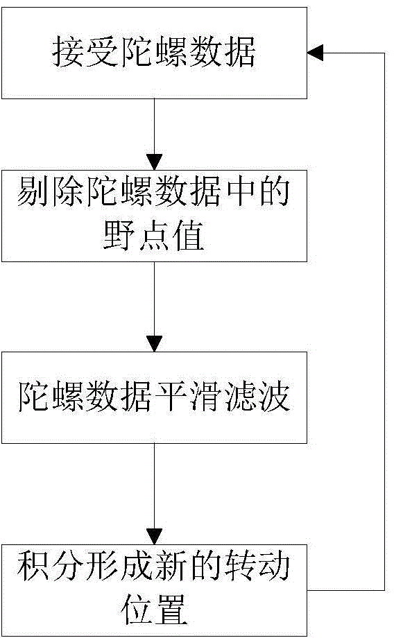
The invention provides a position control method based on fiber-optic gyroscope integral means. Firstly, output data of M periods of a fiber-optic gyroscope are collected consecutively, outliers are removed from the output data, zero-bias stability Bs of the fiber-optic gyroscope is calculated according to n output data W1', W2'...Wn' with outliers removed. Secondly, smoothing filtering is carried out on the data of the fiber-optic gyroscope after outlier removal. At last, a transposition angle value of a servo-stabilization platform is obtained by integrating the angular rate wp of the fiber-optic gyroscope after smoothing filtering is carried out. The position control method based on the fiber-optic gyroscope integral means can be widely applied to a position twirl control system of a milliradian grade, for example a photoelectric instrument indicated by a helmet and a camera system indicated by a radar. Turning precision of 1 mrad can be qualified for introducing an objective to fields of view through position twirl. If no target indication high precision is required, optoelectronic equipment of this kind can entirely adopts the technology, and utilization of a light code disc or a resolver can be omitted; equipment cost can be saved.

Description

technical field [0001] The invention belongs to the technical field of optical aiming and position control, and in particular relates to a method for realizing position control by using an optical fiber gyroscope. Background technique [0002] Precision strike is one of the main characteristics of the evolution and development of modern weapons and equipment. Precision strike in motion is the basic requirement for tactical weapons. Stabilized aiming system is an important organizational part of precision strike tactical weapon system. In modern warfare, weapons equipped with optoelectronic devices such as advanced forward-looking infrared systems, infrared search and tracking systems, low-light television equipment, laser ranging / target indication systems, and laser automatic tracking systems are used in reconnaissance, night combat, air strikes, and air combat. played an important role in both. Steady aiming technology is an indispensable key technology for optoelectronic ...

Claims


Application Information

Patent Timeline
Patent Type & Authority Applications(China)
IPC IPC(8): G05D1/10
Inventor 贺峻峰朱建军许开銮张建峰易科尹剑周国良马忠孝李颖娟陈颖康臻张夏疆杨萌陈红康婷颋黄皓
Owner 西安应用光学研究所
Learn More