Self-adjusting wireless charging system and method for electric automobile

A technology for electric vehicles and wireless charging, which is applied to electric vehicles, electromagnetic wave systems, battery circuit devices, etc., can solve the problems of no uniform standard for receiving coils, real-time adjustment of transmitting coils, and short electromagnetic induction transmission distance, etc. Lifespan, avoiding wear and tear of charging connection equipment, and improving safety and reliability effects

Active Publication Date: 2015-04-22
NORTHEASTERN UNIV
View PDF9 Cites 35 Cited by
  • Summary
  • Abstract
  • Description
  • Claims
  • Application Information

AI Technical Summary

Problems solved by technology

[0002] Wireless power transmission technology can effectively overcome the problems of poor mobile flexibility of traditional power supply, unsightly environment, easy contact sparks, and exposure of power supply lines, etc., and then eliminate the potential safety hazards of traditional power supply methods, making the entire power supply process safer; At present, wireless power transmission can be roughly divided into: electromagnetic induction type, electromagnetic radiation type and electromagnetic resonance type; electromagnetic induction type has short transmission distance and low efficiency; electromagnetic radiation type has long transmission distance, low transmission efficiency, and transmission power is milliwatt level; magnetic Coupled resonant type enables efficient energy transfer over a range of several meters
[0003] Due to changes in external conditions and changes in the coils of different electric vehicles, the resonant frequency will change accordingly, resulting in a decrease in power transmission efficiency. Therefore, the charging device must adapt to different power receiving devices of different electric vehicles. At the same time, the charging device should be in accordance with the battery. Adaptive adjustment of frequency and position according to the requirement of charging law
[0004] At present, the magnetic coupling resonant electric vehicle wireless charging method mostly emphasizes the symmetry of the transmitting coil and the receiving coil. In order to avoid the fact that the transmitting coil and receiving coil adopt the same resonant frequency for maximum power transmission; for example, CN 102969776A and other patents use LC compensation circuits to compensate the resonance parameters of the transmitting coil and receiving coil to maximize the transmission efficiency; CN 103516354A and other patents The frequency tracking method is used to control the switching frequency of the inverter to achieve the purpose of tracking the resonant frequency. However, when the difference between the transmitting and receiving coils is large, especially when the position of the car parks makes the alignment of the transmitting and receiving coils deviate greatly, it is difficult to obtain ideal compensation. and tracking effect; CN 102035239A, CN 103427464A, CN 103401320A and other patents introduce the best alignment or distance between the transmitting coil and the receiving coil or axis by controlling the up and down, left and right, or forward and backward movement of the transmitting coil, but these Most of the patents use sensors for positioning, and only move to a suitable position through a mechanical device and then remain in a static state. When the battery power changes during charging or the parameters of the receiving coil are different, the position of the transmitting coil cannot be adjusted in real time according to these changes. , therefore, there is an urgent need for a self-adjusting wireless charging system for electric vehicles to overcome the above problems

Method used


Image

  • Self-adjusting wireless charging system and method for electric automobile
  • Self-adjusting wireless charging system and method for electric automobile
  • Self-adjusting wireless charging system and method for electric automobile

Examples


Embodiment Construction

[0049] An embodiment of the present invention will be further described below in conjunction with the accompanying drawings.

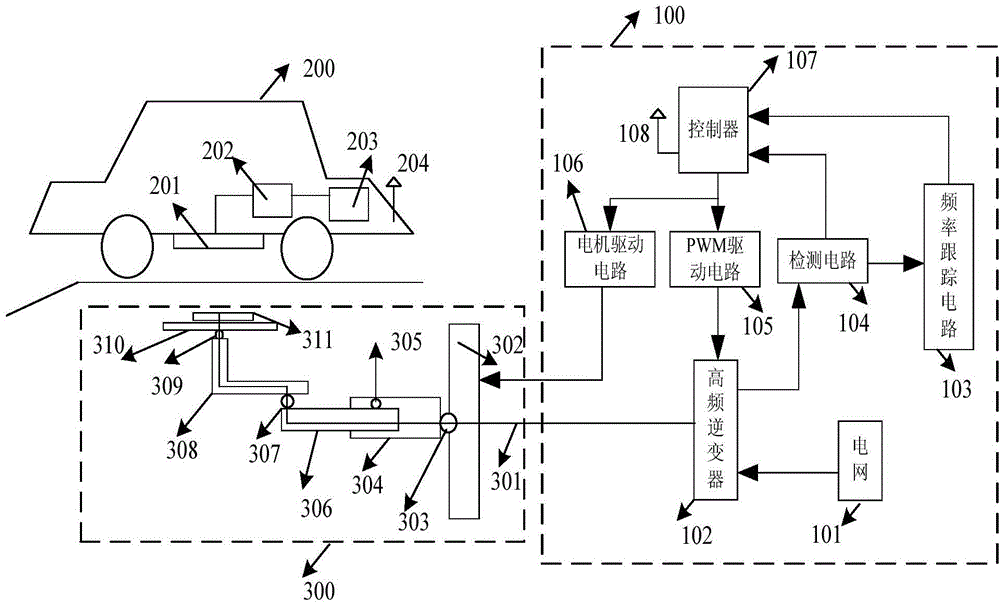
[0050] Such as figure 1 As shown, in the embodiment of the present invention, the electric vehicle self-adjusting wireless charging system includes a wireless power generating device 100 disposed inside the charging pile, a wireless power receiving device 200 and a power transmitting device 300 disposed inside the electric vehicle; the wireless power generating device 100 is located on the charging station, and is used to generate high-frequency electric energy, and transmit electric energy to the electric energy receiving apparatus 200 through the electric energy transmitting apparatus 300 and the magnetic coupling resonance method according to the battery information of the electric energy receiving apparatus 200;

[0051] Such as figure 1 As shown, the wireless power generation device includes a controller 107, a motor drive circuit 106, a PWM driv...


PUM


Abstract

The invention relates to a self-adjusting wireless charging system and method for an electric automobile and belongs to the technical field of electric automobile charging. Compared with a wired charging system, the operability of the wireless charging system is simpler. When the distance between a transmitting coil and a receiving coil is within the range of 50 cm, high-efficiency power transmission can be achieved. A variable current load tracking charging mode is further contained, charging can be performed according to the optimal charging current curve, so the service life of a battery is prolonged. Wireless charging is independent of automobile model numbers and the size and the shape of an energy receiving unit, so the electric automobile can charge the battery without depending on external connection equipment. In addition, according to the self-adjusting wireless charging system and method, a wireless power generation device and a wireless power receiving device can be in real-time communication, and the output power of the wireless power generation device can be adjusted according to the state of the battery, so the control mode of load tracking is achieved; the self-adjusting wireless charging system and method enable charging equipment to be higher in reliability and longer in service life, can meet the requirement for electric automobile charging of clients and is high in charging efficiency and practicality.

Description

technical field [0001] The invention belongs to the technical field of electric vehicle charging, and in particular relates to an electric vehicle self-adjusting wireless charging system and method. Background technique [0002] Wireless power transmission technology can effectively overcome the problems of poor mobile flexibility of traditional power supply, unsightly environment, easy contact sparks, and exposure of power supply lines, etc., and then eliminate the potential safety hazards of traditional power supply methods, making the entire power supply process safer; At present, wireless power transmission can be roughly divided into: electromagnetic induction type, electromagnetic radiation type and electromagnetic resonance type; electromagnetic induction type has short transmission distance and low efficiency; electromagnetic radiation type has long transmission distance, low transmission efficiency, and transmission power is milliwatt level; magnetic Coupled resonan...

Claims


Application Information

Patent Timeline
Patent Type & Authority Applications(China)
IPC IPC(8): H02J7/02H02J17/00H02J50/10
Inventor 王安娜赵强王浩曲艳华林盛
Owner NORTHEASTERN UNIV
Why Eureka
Try Eureka