Slope compensation control method and circuit for inverted welding power source with peak current control mode

A technology of inverter welding power supply and peak current control, which is applied to welding equipment, arc welding equipment, and conversion equipment with intermediate conversion to AC, etc. It can solve the problem of increasing the pressure of switching devices, increasing the current of switching devices, and the space radiation of inductive magnetic field And the problems of unfavorable conduction, energy saving and environmental protection of inverter welding power supply, etc., to achieve high reliability, solve sub-harmonic oscillation, and improve the effect of anti-bias magnetic ability

Inactive Publication Date: 2015-04-22
HANGZHOU KAIERDA ELECTRIC WELDING MACHINE
View PDF4 Cites 9 Cited by
  • Summary
  • Abstract
  • Description
  • Claims
  • Application Information

AI Technical Summary

Problems solved by technology

[0003] There are two main ways to realize the current slope compensation of the existing inverter welding power supply: 1. Superimpose the compensation slope on the induced voltage of the sampling resistor to increase the voltage change rate of the feedback signal, and then compare it with the smooth error voltage to adjust Pulse width output, but due to the superimposed additional current slope signal, the current of the power device cannot be truly reflected; second, adding an...

Method used


Image

  • Slope compensation control method and circuit for inverted welding power source with peak current control mode
  • Slope compensation control method and circuit for inverted welding power source with peak current control mode
  • Slope compensation control method and circuit for inverted welding power source with peak current control mode

Examples


Embodiment Construction

[0018] The present invention will be further described below in conjunction with the accompanying drawings, but the present invention is not limited to the following examples.

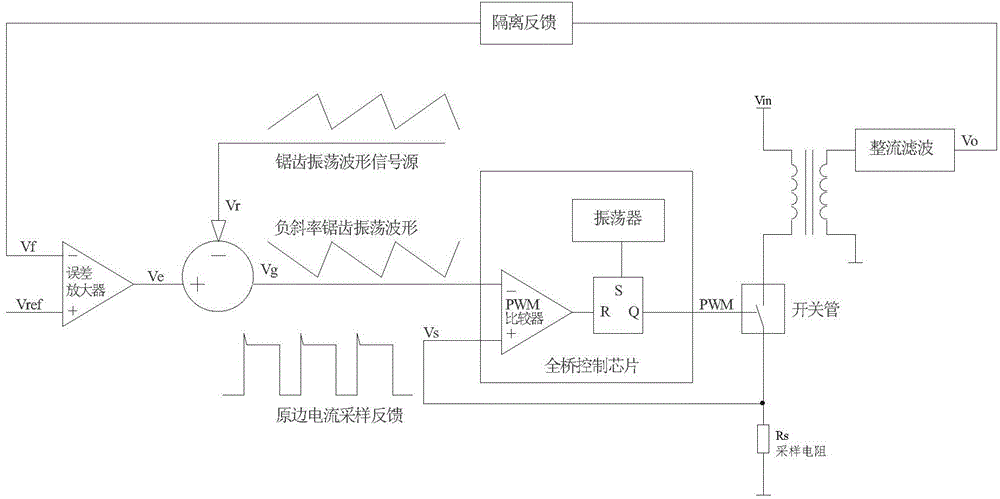
[0019] Such as figure 1 As shown, the present invention provides a slope compensation control circuit of a peak current control mode inverter welding power supply, including a full bridge control chip, an error amplifier, a sampling resistor Rs, a switch tube, and an arithmetic unit (LF353 , LF347 and other operational amplifiers with a gain-bandwidth product greater than 3MHz), a transformer, a rectifier filter circuit, and an isolated feedback circuit.

[0020] The full-bridge control chip is at least integrated with an oscillator, a PWM comparator, and a constant-frequency clock pulse setting R-S latch. The negative input terminal of the full-bridge control chip (i.e. the negative pin of the PWM comparator) is connected to the output terminal of the arithmetic unit, thereby introducing the voltage ...


PUM


Abstract

The invention relates to a slope compensation control method and a circuit for an inverted welding power source with a peak current control mode. The purpose of the slope compensation control method and the circuit is to effectively solve the sub-harmonic oscillation by providing a control method and a control circuit, to truly reflect the electric current of a power device, and to improve the anti-magnetic biasing capability of a system and the real-time protecting capability of the electric current of the power device. According to the technical scheme, the slope compensation control method and the circuit for the inverted welding power source with peak current control mode is characterized in that addition and subtraction are conducted between a saw-tooth oscillation waveform outputted by an input saw-tooth waveform signal source and a voltage signal outputted by an error amplifier, so that a voltage signal of a negative slope saw-tooth waveform is obtained. The voltage signal of the negative slope saw-tooth waveform is compared in real-time with a sampling feedback signal of a voltage input side current. Accordingly, the PWM pulse width output can be adjusted.

Description

technical field [0001] The invention relates to the technical field of inverter welding power supplies, in particular to a slope compensation control method for an inverter welding power supply in a peak current control mode, and a slope compensation control circuit for an inverter welding power supply in a peak current control mode. Background technique [0002] In the inverter welding power supply, the control methods of the DC-DC power converter can be divided into two categories: voltage mode and current mode, and the current mode control is further divided into peak current control and average current control. Compared with the voltage mode, the peak current control technology is widely used because of its fast dynamic response, good adjustment performance, easy implementation of current limiting and overcurrent protection, automatic anti-bias and easy current sharing. However, in the peak current mode, when the duty cycle is greater than 50%, there are problems such as...

Claims


Application Information

Patent Timeline
IPC IPC(8): H02M3/28B23K9/10
Inventor 侯润石兰照丹王青青王海辉王光辉吴勇健
Owner HANGZHOU KAIERDA ELECTRIC WELDING MACHINE
Why Eureka
Try Eureka