Bone drill with stopping function

A bone drill and functional technology, which is applied in the field of bone drills with self-stop function, can solve the problems of increasing operation time and strength, reducing the service life of high-precision bone drills, and prolonging the time of patients in bed, so as to facilitate treatment and reduce medical treatment. Risk, effectiveness of reducing operational difficulty and risk

Inactive Publication Date: 2015-04-29
SHANGHAI JIAO TONG UNIV
View PDF4 Cites 8 Cited by
  • Summary
  • Abstract
  • Description
  • Claims
  • Application Information

AI Technical Summary

Problems solved by technology

The disadvantages of this method are: (1) increase the operation time and intensity; (2) increase the difficulty of healing due to peeling off the periosteum, and increase the patient's bed rest time
At present, the more advanced bone drills on the market obtain the torque force of the motor through the mechanical structure to achieve the effect of automatic control, but this kind of equipment is not only clumsy, the accuracy is not high, and the function is single. Due to the operator's mistake, it will cause great harm to the patient's bones, and at the same time, it will reduce the service life of the high-precision bone drill equipment, and at the same time, it cannot solve the problem of the momentary feeling of the bone drill penetrating the bone tissue.
[0005] Therefore, those skilled in the art are committed to developing a bone drill with a self-pause function to solve the problem of the moment when the bone drill penetrates the bone tissue.

Method used


Image

  • Bone drill with stopping function
  • Bone drill with stopping function

Examples


Embodiment Construction

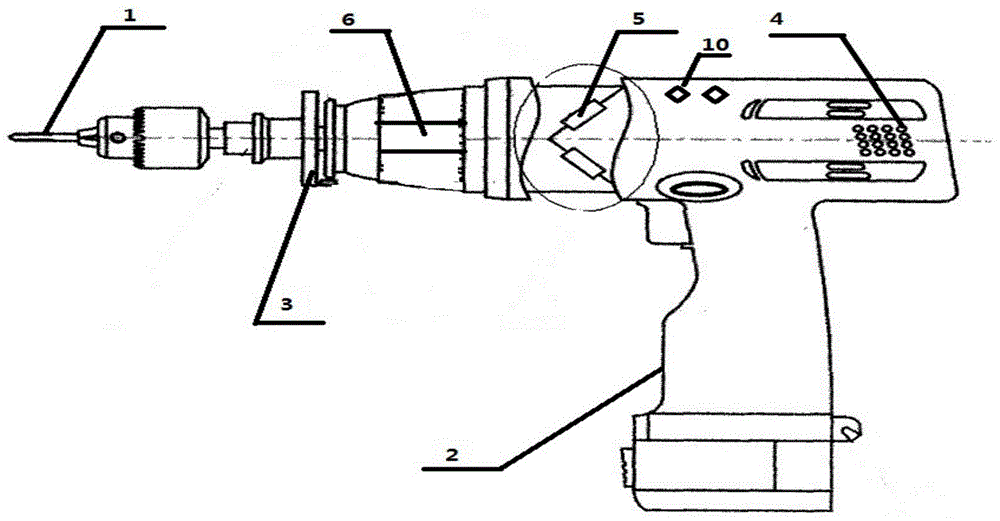
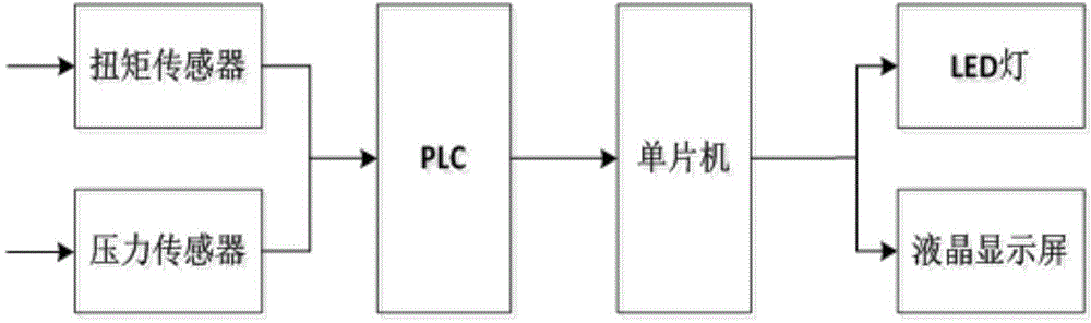
[0025] Such as figure 1 , 2 As shown, in a preferred embodiment of the present invention, the bone drill with self-pause function of the present invention includes a pressure sensor 6, a torque sensor 5, a PLC, a single-chip computer, a relay, an LED 10, a liquid crystal display, and a key board 4.

[0026] Among them, the pressure sensor 6 and the torque sensor 5 constitute the sensor module of the bone drill with self-stop function of the present invention, which is used to obtain the pressure and torque received by the drill bit 1 and to obtain the first electrical signal and the first electrical signal corresponding to the pressure and torque. The second electrical signal is output to the intelligent control module. In this embodiment, three strain gauges are arranged on the same section of the ring member of the motor 3, and the angle with the center axis of the ring member is ±60°, see figure 1 The position of the strain gauge drawn as a square in the circle at the middle to...


PUM


Abstract

The invention discloses a bone drill with a stopping function. The bone drill comprises a sensing module and an intelligent control module. The sensing module comprises a pressure sensor and / or torque sensor which are used for outputting a first electric signal and a second electric signal corresponding to the pressure and torque received by the drill bit of the bone drill. The intelligent control module receives the first electric signal and / or the second electric signal and allows a motor to stop rotating for the first time when the first step descending of the first electric signal and / or the second electric signal occurs; then the intelligent control module starts the motor and allows the motor to stop rotating for the second time when the second step descending of the first electric signal and / or the second electric signal occurs, and the bone drill completes work. Compared with the bone drills in the prior art, the bone drill with the stopping function has the advantages that the operation process of the bone drill is specific and digital, operation difficulties and risks are lowered, medical risks are reduced, and bone treatment by orthopedists is facilitated.

Description

Technical field [0001] The invention relates to the field of medical equipment, and in particular to a bone drill with a self-stop function. Background technique [0002] The treatment of bones is a difficult problem at home and abroad. In the orthopedics department of hospitals, orthopedic drills (abbreviated as bone drills) are one of the commonly used surgical instruments. With the development of science and technology, equipment for drilling bones has come out one after another. However, due to technical limitations, most bone drills currently used in hospitals or on the market are manual equipment. [0003] The safety of manual bone drills is not easy to guarantee, which is mainly reflected in that the drilling depth, electric drill speed, and start-stop control are all controlled by the operator. For the surgical operator, there is a clear sense of frustration at the moment of drilling through. This also results in the high-speed rotation of the bone drill head through the...

Claims


Application Information

Patent Timeline
Patent Type & Authority Applications(China)
IPC IPC(8): A61B17/16
CPCA61B17/1626
Inventor 王景成石伟晶胡涛乐文华刘华江王博辉张浪文
Owner SHANGHAI JIAO TONG UNIV
Why Eureka
Try Eureka