Powder Manufacturing Equipment

A technology for manufacturing equipment and powder, which is applied in the field of powder manufacturing equipment, can solve problems such as difficult heating, uneven temperature distribution, and uneven thermal process, etc., and achieve the effect of suppressing operating costs

Active Publication Date: 2017-05-10
CHUGAI RO CO LTD
View PDF6 Cites 0 Cited by
  • Summary
  • Abstract
  • Description
  • Claims
  • Application Information

AI Technical Summary

Problems solved by technology

[0012] But from another point of view, Patent Document 2, for example, when the volume of the vertical furnace increases as the scale of the vertical furnace increases, the combustion exhaust gas flowing in the vertical furnace will It is prone to bias flow, and it is difficult to uniformly heat the particles of the raw material powder falling in the furnace in a floating state, and there is a problem that the thermal history of the powder is not uniform
[0013] In addition, there is also the following problem: the temperature distribution in the high-temperature processing space is not uniform, and the heat history received by each particle is not uniform depending on which place in the high-temperature processing space the particles of the raw material powder pass through.

Method used


Image

  • Powder Manufacturing Equipment
  • Powder Manufacturing Equipment
  • Powder Manufacturing Equipment

Examples


Embodiment Construction

[0034] Hereinafter, a powder manufacturing apparatus according to a first embodiment of the present invention will be described based on the drawings. In addition, in the following description, although terms indicating directions and positions (for example, "one end" and "another end", "upstream" and "downstream", etc.) are used for convenience, this is to make the invention easier to understand. The meanings of terms do not limit the technical scope of the present invention. In addition, the following description is merely an illustration of one embodiment of the present invention, and is not intended to limit the present invention and its application objects or uses.

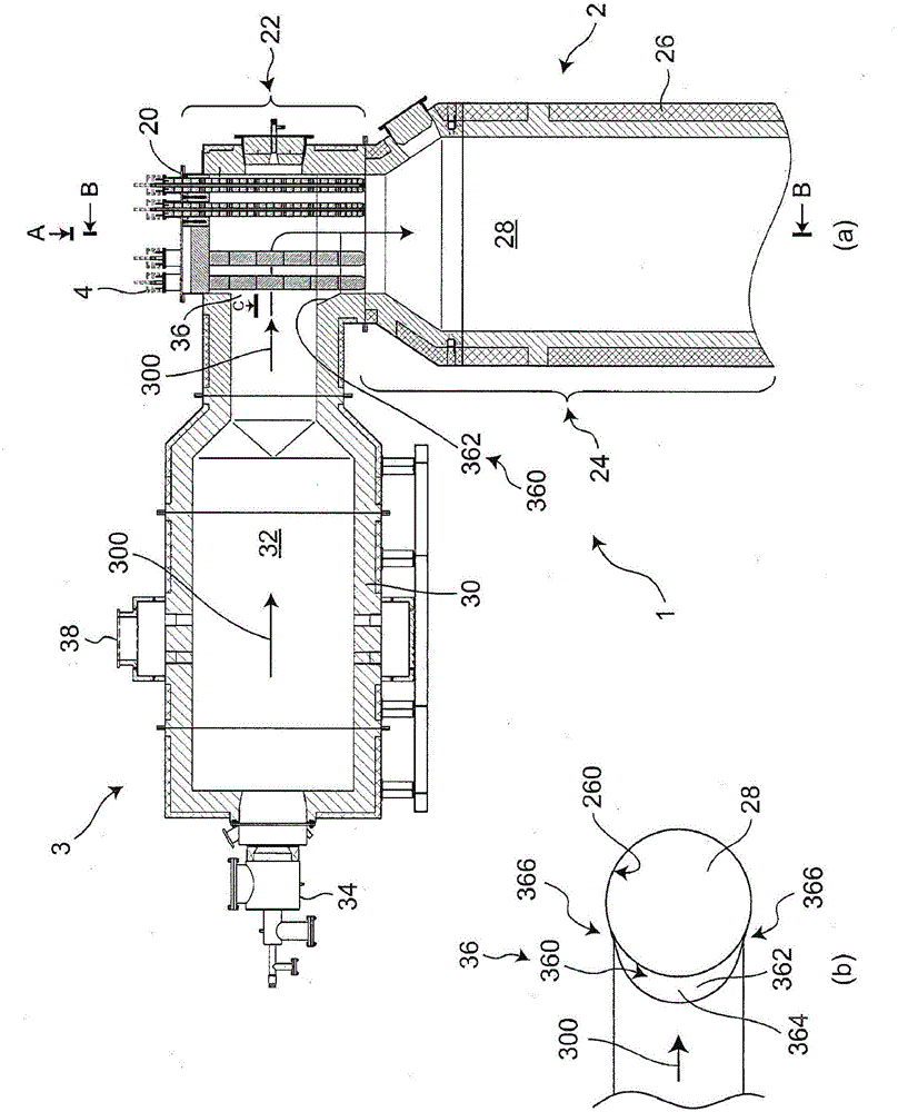
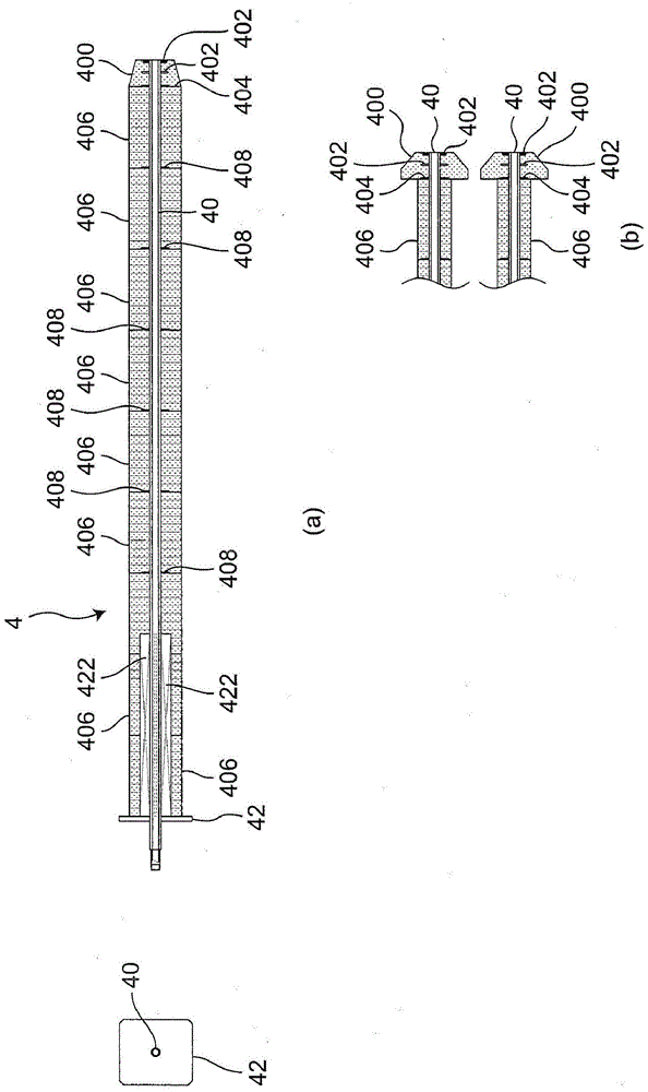
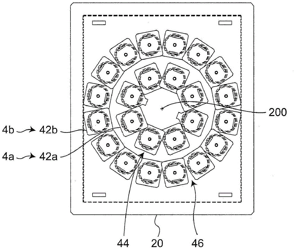
[0035] Such as figure 1 As shown in (a), the powder manufacturing device 1 includes a vertical cylindrical furnace 2, a horizontal cylindrical combustion device 3, and a raw material nozzle 4, and the raw material nozzle 4 is arranged vertically downward in the vertical furnace 2. The top 20 of the furnace,...


PUM


Abstract

The invention provides a powder manufacturing device. The operation cost can be reduced, the bias current, which flows in a vertical furnace, of flue gas can be inhibited, and the particles of raw materials that float in the furnace can be evenly heated by the provided powder manufacturing device. The raw material spouts (4a) that form the first raw material spout array (44) are arranged in an equal distance angle (A). The raw material spouts (4b) that form the second raw material spout array (46) are arranged in an equal distance angle (B). The distance angle (B) is smaller than the distance angle (A). The first raw material spout array (44) and the second raw material spout array (46) are staggeredly arranged to form a half distance angle and the gaps between the spouts are used to discharge the burning gas.

Description

technical field [0001] The invention relates to a powder manufacturing device. Background technique [0002] As a heating method for high-temperature firing, encapsulation, or spheroidization of raw material powder, there are known static heating methods in which powder is filled in a container with a certain capacity and heated in an electric furnace or a kiln, and raw material powder A floating heating method in which the powder is directly thrown into the high-temperature combustion exhaust and the raw material powder is heated in the high-temperature processing space. [0003] As an example of a device using a static heating method, a roller hearth kiln is known. A ceramic container called a saggar filled with powder is placed on a roller. The roller conveys the sagger and heats the sagger to a predetermined temperature (for example, refer to Patent Document 1). [0004] In addition, as an example of a device using a floating heating method, a powder manufacturing devi...

Claims


Application Information

Patent Timeline
Patent Type & Authority Patents(China)
IPC IPC(8): B01J2/00
CPCB01J2/00B01J2208/00B01J19/26
Inventor 友泽健一林佑树
Owner CHUGAI RO CO LTD
Why Eureka
Try Eureka