
Tin-soldering tooling with strip-shaped heat dissipation holes

A strip-shaped, soldering technology, applied in auxiliary devices, manufacturing tools, welding equipment, etc., can solve the problems of reducing work efficiency and achieve the effects of improving soldering efficiency, easy processing, and simple structure

Inactive Publication Date: 2015-04-29
GUIYANG HIGH TECH KINGDA ELECTRONICS TECH
View PDF5 Cites 2 Cited by
  • Summary
  • Abstract
  • Description
  • Claims
  • Application Information

AI Technical Summary

Problems solved by technology

Since the two soldering operations make the soldering tooling very hot and reduce work efficiency, how to dissipate heat from the soldering tooling is a very important design point

Method used


Image

  • Tin-soldering tooling with strip-shaped heat dissipation holes
  • Tin-soldering tooling with strip-shaped heat dissipation holes
  • Tin-soldering tooling with strip-shaped heat dissipation holes

Examples


Embodiment Construction

[0026] The present invention will be described in detail below with reference to the accompanying drawings and examples.

[0027] The present invention provides a soldering tooling for an automatic soldering system for inductors. As shown in the figure, the base 201 of the soldering tooling is a strip-shaped aluminum alloy plate. For the convenience of description, the extension of the strip-shaped aluminum alloy plate is set The direction is the X direction, the plate thickness direction is the Y direction, and the plate width direction is the Z direction.

[0028] A through groove is formed on one of the long sides of the elongated aluminum alloy plate, and inverted T-shaped support platforms 203 are arranged at equal intervals in the groove, and the height of the support platform is the same as the depth of the groove.

[0029] As shown in Figure 3(b), the length of the Y-direction of the top surface of the support platform 203 is smaller than the distance between the two c...


PUM


Abstract

The invention discloses a tin-soldering tooling of an automatic tin-soldering system of an inductor. The tin-soldering tooling can be used for providing a plurality of tin-soldering tooling positions of the inductor at a time, is provided with the heat dissipation design and can also be used for providing the basis for improving the tin-soldering working efficiency. A substrate of the tin-soldering tooling is a strip-shaped aluminum alloy plate, wherein a through groove is formed in one long side of the strip-shaped aluminum alloy plate; inverted T-shaped support tables are arranged in the groove at equal intervals; by designing the distance between two support tables, the inductor is erected between two adjacent support tables by using a boss; the height of the support table meets the condition that a circuit magnetic core in the inductor is not in contact with the bottom of the groove; partition positioning grooves matched with a middle partition of the inductor are distributed in the wall of the groove at equal intervals; circular magnetic steel used for absorbing a circular magnetic core of the inductor is embedded into the bottom of the groove; a plurality of rounded-corner strip-shaped holes penetrating through two large surfaces of the strip-shaped aluminum alloy plate are formed in the strip-shaped aluminum alloy plate; a ring of Teflon high-temperature adhesive tape is wound around one end provided with a groove on the strip-shaped aluminum alloy plate.

Description

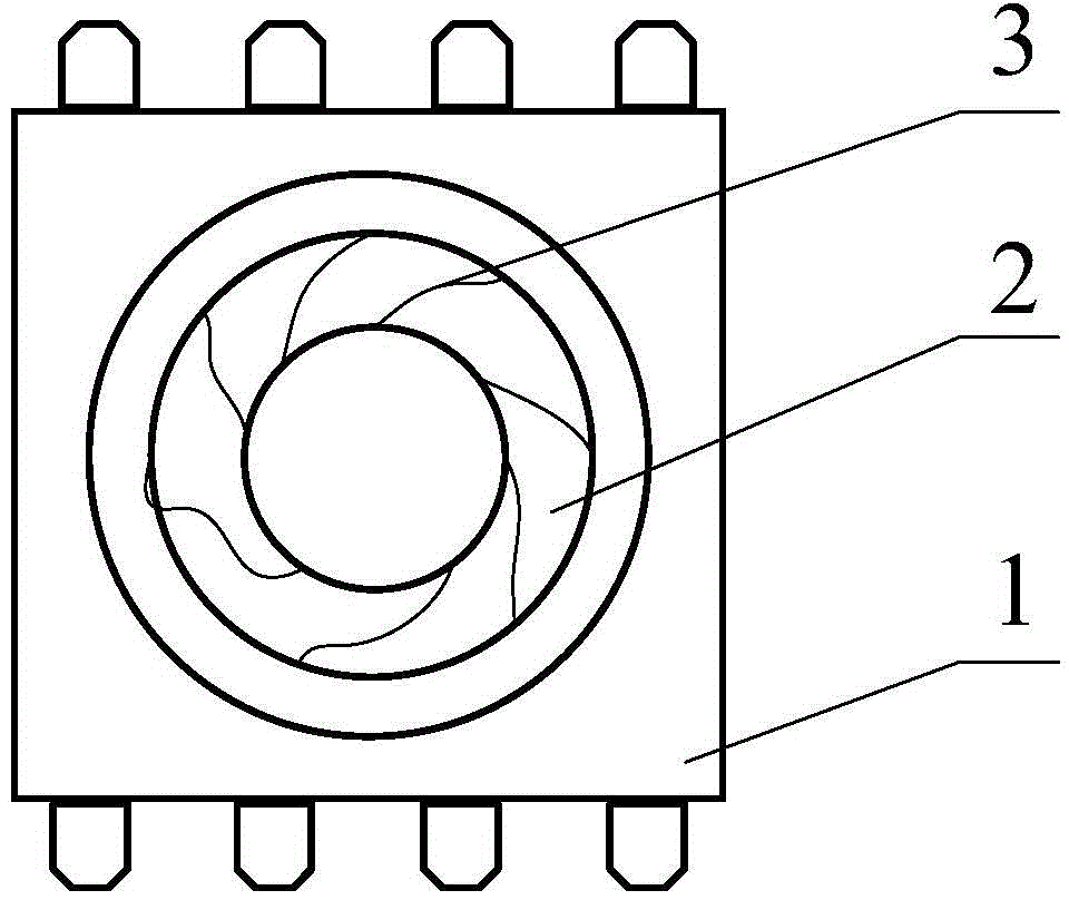
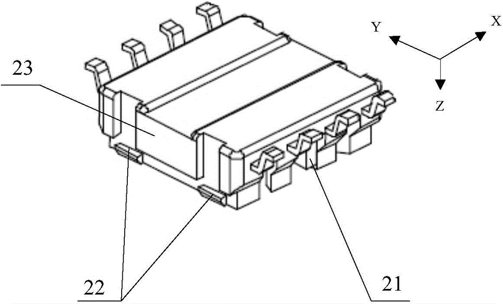
technical field [0001] The invention relates to the technical field of inductor auxiliary tools, in particular to a soldering tool for an inductor automatic soldering system. Background technique [0002] Inductors are components that can convert electrical energy into magnetic energy and store it. The structure of the inductor includes a base 1 , a circular magnetic core 2 and a winding 3 . like figure 1 As shown, the winding 3 is wound around the circular magnetic core 2 and embedded in the base 1 for packaging. Winding 3 is generally enameled wire. Wherein, the concrete structure of the inductor that the present invention relates to is: see figure 2 As shown in the back view of the base 1 , there are 4 pins on both sides of the base 1 , and the middle two pins are separated by the middle barrier 21 processed on the base 1 . The direction in which pins are arranged is the length direction X, the other direction is the width direction Y, and the thickness direction of...

Claims


Application Information

Patent Timeline
Patent Type & Authority Applications(China)
IPC IPC(8): B23K3/08B23K37/04H01F41/00
Inventor 郑应华晋家贵李军飞
Owner GUIYANG HIGH TECH KINGDA ELECTRONICS TECH
Learn More