Finish machining device for wire-drawing die

A wire drawing die and wire drawing technology, applied in the direction of grinding drive devices, metal processing equipment, manufacturing tools, etc., can solve problems such as low processing efficiency, roughness, and complex structure, and achieve good finishing effect, high processing efficiency, and reasonable design Effect

Inactive Publication Date: 2015-04-29
天长市天屹模具科技发展有限公司
View PDF6 Cites 17 Cited by
  • Summary
  • Abstract
  • Description
  • Claims
  • Application Information

AI Technical Summary

Problems solved by technology

[0005] However, the inside of the wire drawing die on the multi-functional area has many turns and is rough. If it cannot be polished carefully, it will have an adverse effect on...

Method used


Image

  • Finish machining device for wire-drawing die
  • Finish machining device for wire-drawing die
  • Finish machining device for wire-drawing die

Examples


Embodiment Construction

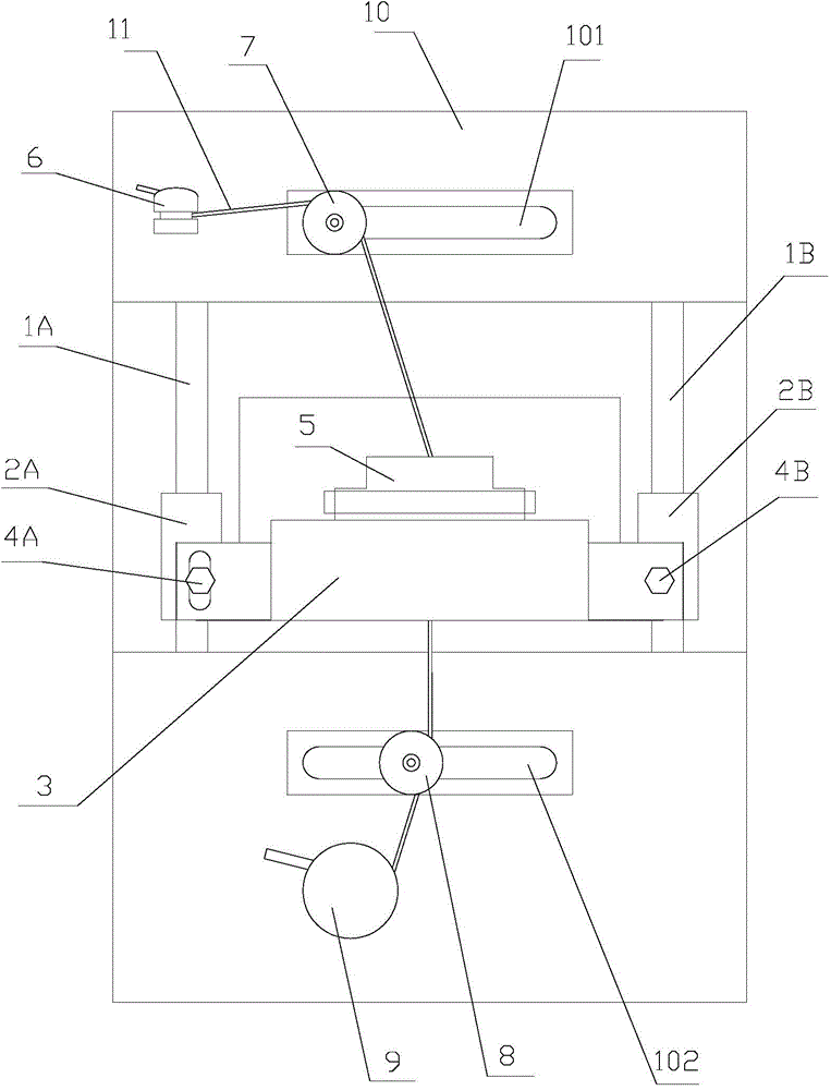
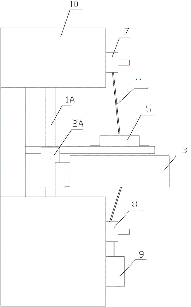
[0018] Such as figure 2 with image 3 As shown, a wire drawing die finishing device proposed by the present invention includes: a first slide bar 1A, a second slide bar 1B, a slide frame 2, a carrier plate 3, a first screw 4A, a second screw 4B, a clamp 5, The first wire winding machine 6, the first wire drawing reel 7, the second wire drawing reel 8, the second wire winding machine 9, the support 10, the wire 11, the first driving mechanism and the second driving mechanism.

[0019] The first slide bar 1A and the second slide bar 1B are arranged in parallel and installed vertically on the bracket 10. The slide frame 2 is made up of the first slide block 2A, the second slide block 2B and the connecting arm. The first slide block 2A and the second slide bar The slider 2B is fixedly connected as a whole through the connecting arm, and through holes are provided in the first slider 2A and the second slider 2B, and the first slider 2A and the second slider 2B are respectively sl...


PUM


Abstract

The invention provides a finish machining device for a wire-drawing die. The finish machining device for the wire-drawing die comprises a first sliding rod, a second sliding rod, a sliding support, a bearing tray, a first screw, a second screw, a fixture, a first wire winder, a first wire leading tray, a second wire leading tray, a second wire winder, a bracket, a silk yarn, a first driving mechanism and a second driving mechanism, wherein the first driving mechanism controls the sliding support to vertically slide along the first sliding rod and the second sliding rod; the wire-drawing die vertically slides along with the sliding support; the second driving mechanism drives the fixture to rotate and drives the wire-drawing die to rotate, i.e., the second driving mechanism drives the wire-drawing die to be processed to vertically slide and rotate, so that the silk yarn fully polishes a functional surface of the contacted wire-drawing die to realize the finish machining of a wire-drawing hole in the wire-drawing die. The wire-drawing die disclosed by the invention has the advantages of simple structure, high processing efficiency and good finish processing effect, and requirements on the finish machining of the multifunctional surface of the wire-drawing hole in the wire-drawing die is realized.

Description

technical field [0001] The invention relates to the field of wire drawing die processing, in particular to a wire drawing die finishing device. Background technique [0002] Drawing dies are widely used, such as processing high-precision wires used in electronic devices, radar, television, instruments and aerospace, as well as commonly used tungsten wires, molybdenum wires, stainless steel wires, wire and cable wires and various alloy wires. made. [0003] At present, there are countless manufacturers of wire drawing dies for metal wire forming, with different production processes and tools, but most of the wire drawing dies are relatively simple in design, single in die hole structure, rough in the angle design of each working area, and cannot be accurately implemented. Division of regional functions. Therefore, in the high-end metal wire forming production with high precision requirements, the wire drawing dies produced by the prior art cannot accurately control the wire...

Claims


Application Information

Patent Timeline
IPC IPC(8): B24B5/48B24B47/16
CPCB24B5/48B24B47/16
Inventor 朱家德王子尊许会子房如勤
Owner 天长市天屹模具科技发展有限公司
Why Eureka
Try Eureka