Robot joint torque limiting device

A technology of robot joints and limiting devices, applied in the field of robots, can solve the problems of limited transmission torque, high precision and small size

Active Publication Date: 2015-04-29
TSINGHUA UNIV
View PDF9 Cites 6 Cited by
  • Summary
  • Abstract
  • Description
  • Claims
  • Application Information

AI Technical Summary

Problems solved by technology

The patent document published on November 27, 2013 as CN203313035U discloses an inter-axial permanent magnetic coupling mechanism, and the patent document published on June 19, 2013 as CN203014642U An inter-shaft per

Method used


Image

  • Robot joint torque limiting device
  • Robot joint torque limiting device
  • Robot joint torque limiting device

Examples


Embodiment Construction

[0017] The robot joint torque limiting device according to the present invention will be described in detail below with reference to the accompanying drawings.

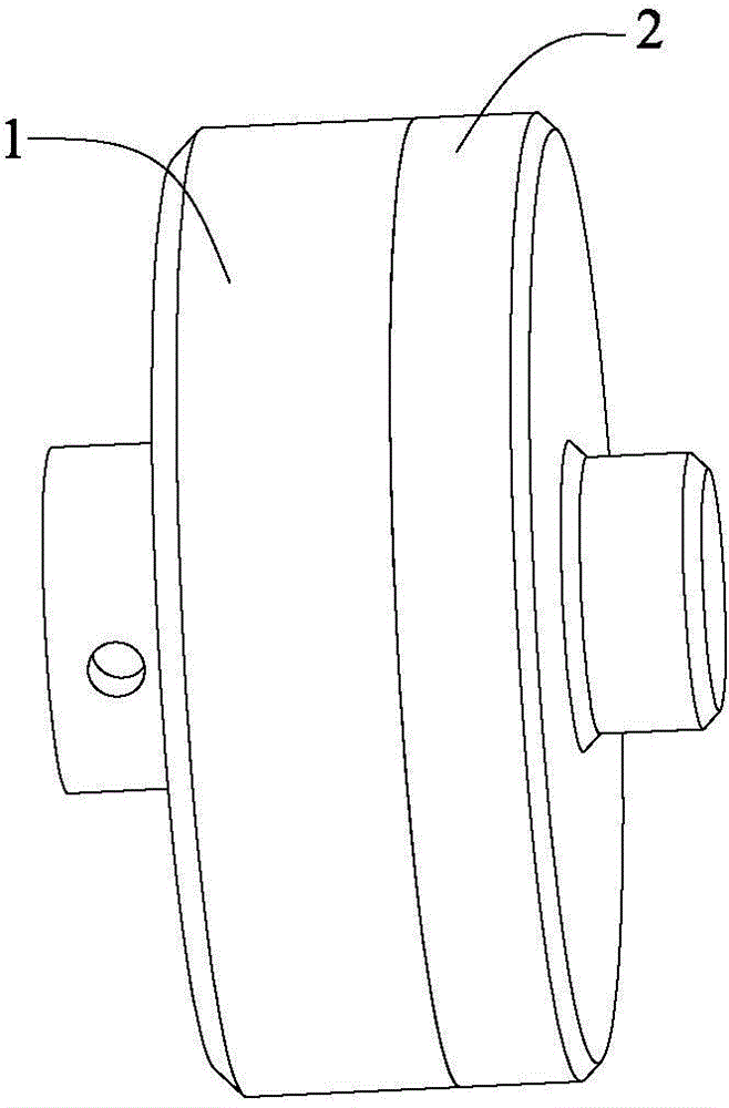
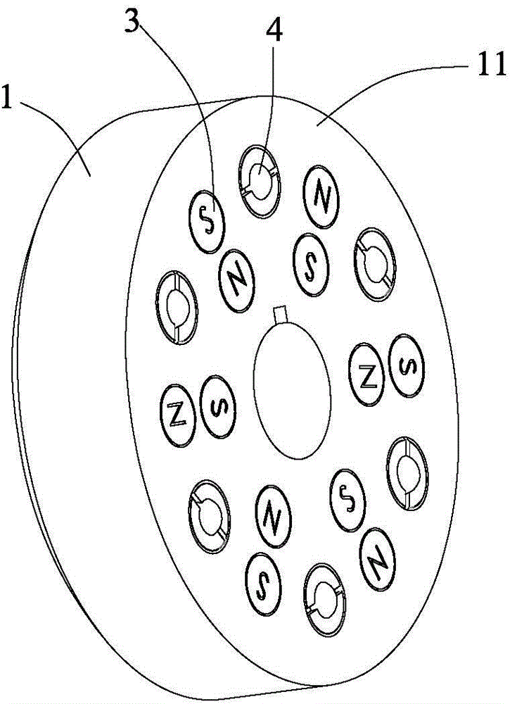
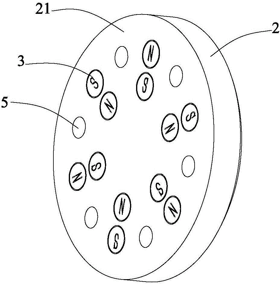
[0018] refer to Figure 1 to Figure 4 , the robot joint torque limiting device according to the present invention includes: an input disk 1, connected to a power input shaft (not shown); an output disk 2, coaxial with the input disk 1, connected to a power output shaft (not shown); The permanent magnet 3 is evenly arranged on the end face 11 of the input disk 1 opposite to the output disk 2, the magnetic pole (N pole or S pole) of the permanent magnet 3 faces the output disk 2, and the magnetic pole of the adjacent permanent magnet 3 The direction is opposite; a plurality of ball plungers 4 are fixedly arranged on the end face 11 of the input disk 1 provided with a permanent magnet 3, and the ball head of the ball plunger 4 is exposed on the end face 11; and a plurality of ball sockets 5, the number The same number a...


PUM


Abstract

The invention provides a robot joint torque limiting device, which comprises an input circular disc, an output circular disc, permanent magnets, a plurality of ball plungers and a plurality of ball sockets, wherein the input circular disc is connected with a power input shaft, the output circular disc is coaxial with the input circular disc and is connected with a power output shaft, the permanent magnets are uniformly arranged at the end surface, opposite to the output circular disc, of the input circular disc , the magnetic poles of the permanent magnets face the output circular disc, the magnetic poles of the adjacent permanent magnets are opposite, the ball plungers are fixedly arranged at the end surface, provided with the permanent magnets, of the input circular disc, a ball of each ball plunger exposes out of the end surface, the number of the ball sockets is the same as the number of the ball plungers, the ball sockets are uniformly arranged at the end surface, opposite to the input circular disc, of the output circular disc, the diameter of the ball of each ball plunger is the same as the diameter of the corresponding ball socket, and the ball of each ball plunger on the input circular disc is attached to the corresponding ball socket on the output circular disc when the input circular disc and the output circular disc are attracted by the permanent magnets. The robot joint torque limiting device has the advantages that the structure is simple, the size is small, the transfer torque is large, and the overload torque is adjustable.

Description

technical field [0001] The invention relates to the technical field of robots, in particular to a robot joint torque limiting device. Background technique [0002] During the movement of a robot, especially a walking robot, when the ground is uneven or the foothold does not match the planned foothold, the foot of the robot will often receive a relatively large impact, and the impact force will be transmitted to each joint, and its It is easy to cause joint damage, especially the gear meshing part of the joint reduction system. At present, most of the joint torque limiters sold in the market are mainly friction clutches and magnetic couplers. Under the premise of transmitting the same torque, they are huge in size, which is not conducive to the miniaturization of robot joints. [0003] Through the investigation of existing patents, it is found that almost all relevant patents are some partial improvements made on the basis of existing mature products to meet specific require...

Claims


Application Information

Patent Timeline
IPC IPC(8): B25J17/00
Inventor 伊强王国磊徐静缪东晶陈恳
Owner TSINGHUA UNIV
Why Eureka
Try Eureka