
External protection system for silicon cutting machine tool

A protection system, silicon cutting technology, applied in the direction of fine working devices, working accessories, stone processing equipment, etc., can solve the problems of inconvenient installation and operation, laborious opening and closing of doors, and large protective body, so as to achieve the effect of convenient observation

Active Publication Date: 2015-04-29
DALIAN GUANGYANG SCI & TECH ENG CO LTD
View PDF7 Cites 6 Cited by
  • Summary
  • Abstract
  • Description
  • Claims
  • Application Information

AI Technical Summary

Problems solved by technology

[0004] The present invention aims at the above-mentioned protection body is very large, opening and closing the door is very laborious, the operator cannot directly observe the internal conditions of the machine tool when the machine tool is working, and the protection of the cutting area can only increase the protection, which makes the machine tool operating space narrow and inconvenient for installation and operation. To solve the technical problem, a split protective cover is proposed, and the parts and parts are connected with the frame by screws, and are installed on the machine tool as a whole or in part.

Method used


Image

  • External protection system for silicon cutting machine tool
  • External protection system for silicon cutting machine tool
  • External protection system for silicon cutting machine tool

Examples


Embodiment Construction

[0029] Note: The direction word "front" proposed in this paper refers to the end of the machining area of ​​the machine tool, that is, the front of the axial direction of the spindle, "rear" is the opposite end to "front", and "left" and "right" are the main Left and right in the view.

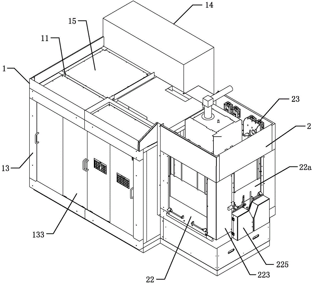
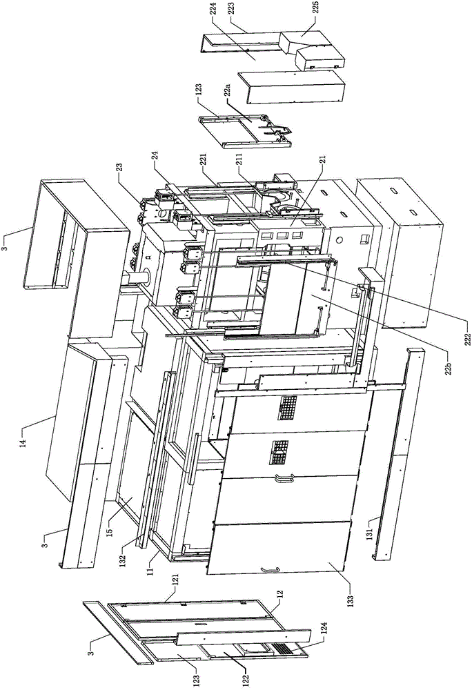
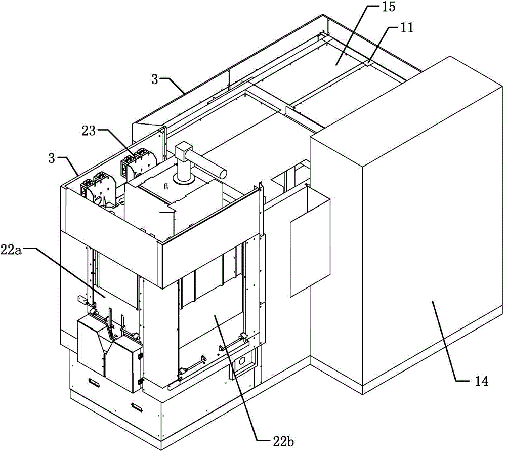
[0030] Such as figure 1 , figure 2 , image 3 with Figure 4 The external protective system for the silicon cutting machine tool shown includes the machine bed protective cover 1 and the machine tool processing area protective cover 2;

[0031] Machine tool bed protective cover 1 comprises: cover as the machine bed external frame 11 outside the machine bed, be fixed on the rear end protection mechanism 12 of bed external frame 11 rear ends, left side protection mechanism 13, right side protection mechanism 14 and be fixed on The top sealing plate 15 at the top of the outer frame 11 of the bed, wherein the structure of the top sealing plate 15 is selectively assembled according to the actu...


PUM

PropertyMeasurementUnit
diameteraaaaaaaaaa

Abstract

The invention discloses an external protection system for a silicon cutting machine tool. According to the self characteristics of the machine tool, protection covers are divided into a machine tool body protection cover and a machine tool machining area protection cover; the two protection covers are connected and fixed with a machine tool body through a frame; the machine tool body protection frame and the machine tool machining area protection frame are subjected to split design so as to facilitate detachable assembly of the protection covers and the frame per se and flexible arrangement of a protection area; the machining area protection cover adopts a balancer sliding door, and gravity balance in a process of lifting the machine tool machining area protection cover is realized through lifting a balancer in a machine tool processing area so as to ensure a labor saving effect of the machine tool machining area protection cover in a lifting process and real-time positioning in a lifting process of the protection cover in a machining process and facilitates to observe the machining area; the whole protection covers and various parts are connected by means of screws and are thus convenient to disassemble, mount and maintain, materials are saved, the space is reduced and the structure of the machine tool is more compact.

Description

technical field [0001] The invention relates to the field of machine tool protection, in particular to an external protection system for silicon cutting machine tools. Background technique [0002] The silicon cutting machine tool is used to cut ultra-thin monocrystalline silicon wafers. The cutting machine tool uses water-based cutting fluid to cut and produce silicon powder. The cutting area of ​​the machine tool has strict requirements. There is steel wire cutting in the cutting area, and the diameter of the steel wire is ¢0.1-0.145mm. [0003] Most of the current machine tool protections are mostly welded and mounted on the machine tool as a whole. The structure is single and backward, the body of the protection is very large, and the opening and closing of the door is very laborious. When the machine tool is working, the operator cannot directly observe the internal conditions of the machine tool. The maintenance and replacement of parts is very troublesome. For the p...

Claims


Application Information

Patent Timeline
Patent Type & Authority Applications(China)
IPC IPC(8): B28D7/00B28D5/00
CPCB28D5/0058
Inventor 张辉高德峰胡丹生财有孙永杰姜德彬赵锋马驰张勇黄海滨贾宇军张现飞贺业锋
Owner DALIAN GUANGYANG SCI & TECH ENG CO LTD
Learn More