Hydraulic stirring anaerobic tank

A technology of hydraulic stirring and anaerobic tank, applied in the field of anaerobic tank, can solve the problems of inability to discharge supernatant, growth inhibition of anaerobic bacteria, no longer existence of supernatant, etc., so as to improve biogas production efficiency and anaerobic Oxygen efficiency, simple structure effect

Active Publication Date: 2017-02-22
WEIFANG JINSIDA NEW ENERGY SCI & TECH
View PDF6 Cites 0 Cited by
  • Summary
  • Abstract
  • Description
  • Claims
  • Application Information

AI Technical Summary

Problems solved by technology

[0003] Most of the existing technologies use mechanical stirring, that is, a propeller is installed in the anaerobic tank, which is driven by a motor outside the tank to rotate to stir the digestion mixture. The disadvantages are: 1. The transmission part is easy to wear and the maintenance is extremely difficult; 2. It is easy to cause the anaerobic bacteria in the anaerobic decomposition zone to enter the acidification reaction zone, resulting in the growth inhibition of anaerobic bacteria; 3. When stirring, the supernatant no longer exists, the supernatant cannot be discharged, and the anaerobic tank cannot work continuously

Method used


Image

  • Hydraulic stirring anaerobic tank
  • Hydraulic stirring anaerobic tank
  • Hydraulic stirring anaerobic tank

Examples


Embodiment Construction

[0020] Exemplary embodiments according to the present invention will be described in detail below with reference to the accompanying drawings. Here, it should be noted that, in the drawings, the same reference numerals are assigned to components having substantially the same structure and function, and redundant descriptions on components that are substantially the same are omitted in order to make the description more concise.

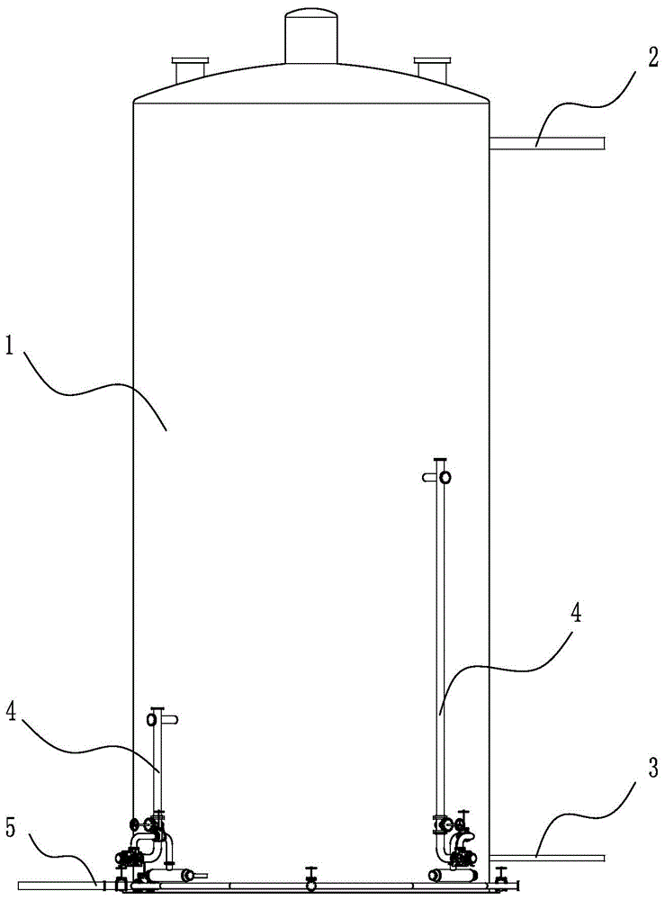
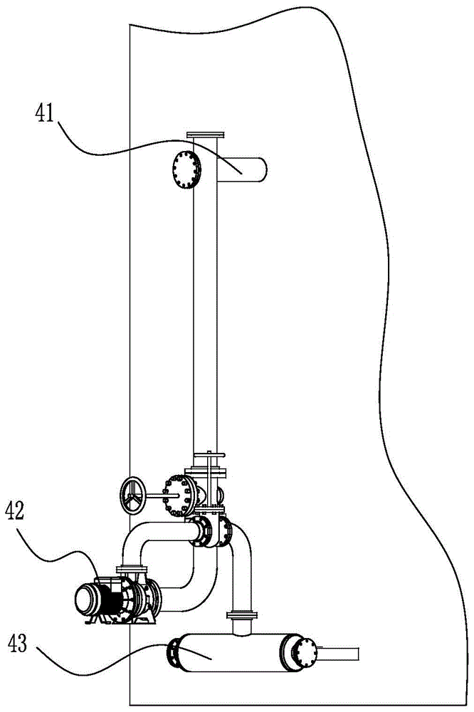
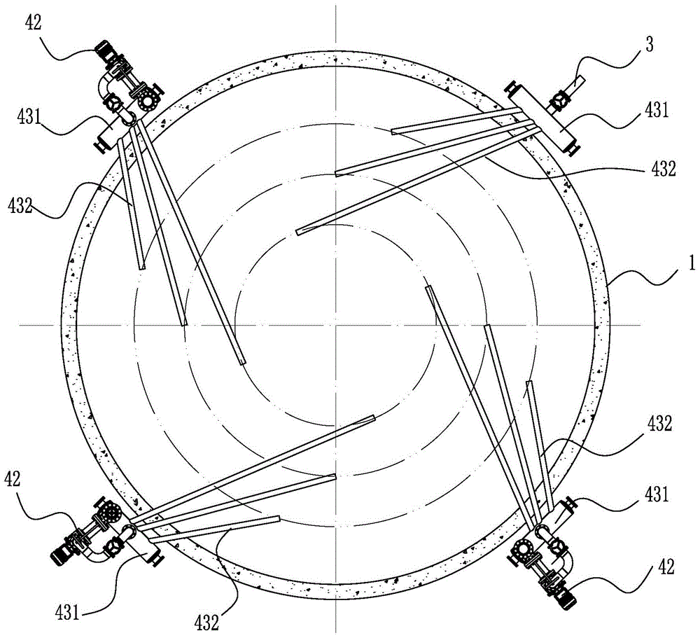
[0021] like figure 1 and figure 2 As shown, the hydraulic agitation anaerobic tank includes a tank body 1, the upper part of the tank body 1 is provided with a supernatant liquid outlet pipe 2, and the bottom part of the tank body 1 is provided with an anaerobic liquid inlet pipe 3, the The bottom of the tank body 1 is provided with a sludge discharge device 5, and at least two hydraulic agitation devices 4 are arranged on the outer peripheral wall of the tank body 1 above the sludge discharge device 5; the hydraulic agitation devices 4 include end ...


PUM


Abstract

The invention discloses a hydraulic stirring anaerobic jar, which comprises a jar body. A sludge discharge device is arranged at the bottom layer of the jar body, at least two hydraulic stirring devices are arranged on the peripheral wall of the jar body above the sludge discharge device in a surrounding manner; each hydraulic stirring device comprises a stirring water pumping pipe, the end part of the stirring water pumping pipe is inserted in the jar body, the stirring water pumping pipe is connected with a sludge pump, and the sludge pump is connected with a swirl generator. According to the hydraulic stirring anaerobic jar, the hydraulic stirring devices pump anaerobic liquid out of an anaerobic decomposition area by utilizing the sludge pump, repeatedly charge the pumped anaerobic liquid into the lower layer in the jar body to form swirls, so that sludge including anaerobe in the lower layer is fully mixed with the anaerobic liquid; along with the cycle operation of the sludge pump, the anaerobe in the anaerobic decomposition area is fully attached to the surfaces of organic matters, so that the anaerobic efficiency is greatly improved; the reaction state of an acidification reaction area is not broken, and meanwhile, the acidification reaction is facilitated; the structure is simple, the maintenance is convenient, and the sludge gas output efficiency of the anaerobic jar is greatly improved.

Description

technical field [0001] The invention relates to the technical field of biogas, in particular to an anaerobic tank. Background technique [0002] The upper part of the anaerobic tank is the acidification reaction zone, and the lower part of the anaerobic tank is the anaerobic decomposition zone. In order to increase the contact between organic matter and anaerobic bacteria, the agitation of the anaerobic tank is the key condition to improve the efficiency of sludge anaerobic digestion. Stirring can Make anaerobic bacteria and organic matter mix quickly, and promote the separation of biogas and digestive juice. [0003] Most of the existing technologies use mechanical stirring, that is, a propeller is installed in the anaerobic tank, which is driven by a motor outside the tank to rotate to stir the digestion mixture. The disadvantages are: 1. The transmission part is easy to wear and the maintenance is extremely difficult; 2. It is easy to cause anaerobic bacteria in the anae...

Claims


Application Information

Patent Timeline
Patent Type & Authority Patents(China)
IPC IPC(8): C12M1/107C12M1/02
CPCC12M21/04C12M27/02C12M29/18
Inventor 刘国田代吉发李振衡
Owner WEIFANG JINSIDA NEW ENERGY SCI & TECH
Why Eureka
Try Eureka