Zinc pot heating radiant tube

A radiant tube, zinc pot technology, applied in hot dip plating process, metal material coating process, coating and other directions, can solve the problems of heat loss, large volatilization, low heating efficiency, etc., to improve temperature uniformity, enhance The effect of heating degree and improving heating efficiency

Active Publication Date: 2015-04-29
CERI PHOENIX INDAL FURNACE CO TD +1
View PDF6 Cites 0 Cited by
  • Summary
  • Abstract
  • Description
  • Claims
  • Application Information

AI Technical Summary

Problems solved by technology

The disadvantages of this method are: 1. It intensifies the corrosion of the molten zinc on the zinc pot; 2. A large amount of heat is lost with the flue gas, and the thermal efficiency of zinc liquid heating is low.
[0005] The upper heating method of the ceramic zinc pot is commonly referred to as reverberatory furnace heating. The gas burner is arranged on the upper part of the ceramic zinc pot, mainly to increase the temperature of the inner surface of the upper cover of the zinc pot (nearly 1100 ° C), and pass through the inner surface of the cover. The heat on the upper surface of the zinc liquid is radiated to realize the heating of the zinc liquid. The disadvantages of this method are: 1. The exhaust gas temperature is high (close to 1100 ° C), a large amount of heat is lost with the flue gas, and the thermal efficiency of the zinc liquid heating Low; 2. Only the upper surface of the zinc solution can be heated, resulting in a large temperature difference between the upper and lower sides of the zinc solution, which affects the quality of galvanized products; 3. The upper surface of the zinc solution has a high temperature and a large amount of volatilization, resulting in waste of zinc
[0006] Due to the unreasonable heating method and the serious corrosion of molten zinc to metal, the current industrial hot-dip galvanizing has the following problems: 1. The waste of pure zinc is large; 2. High energy consumption and low heating efficiency; 3. Poor quality of galvanized products ; 4. Low service life of galvanizing equipment; 5. Serious environmental pollution

Method used


Image

  • Zinc pot heating radiant tube
  • Zinc pot heating radiant tube

Examples


Embodiment Construction

[0039] In order to have a clearer understanding of the technical features, purposes and effects of the present invention, the specific implementation manners of the present invention will now be described with reference to the accompanying drawings.

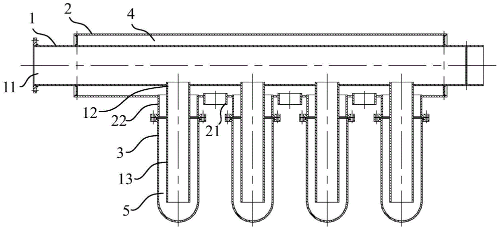
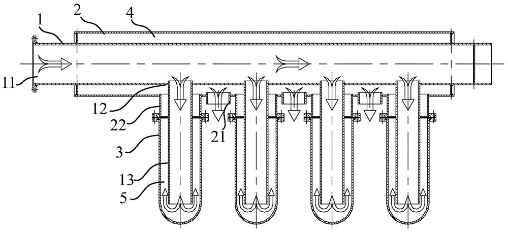
[0040] A kind of zinc pot heating radiant tube of the present invention, as figure 1 As shown, it includes: an inner tube 1, an outer tube 2 and at least one radiant tube 3. One end of the inner pipe 1 is an open end 11, and the other end is a closed end. The open end 11 can be connected with a gas burner; The outer tube 2 is sleeved on the inner tube 1, the two ends of the inner tube 1 extend to the outside of the outer tube 2, and both ends of the outer tube 2 are sealed with the side wall of the inner tube 1; at least one outer tube is provided on the side wall of the outer tube 2 Spout 21. One end of the radiant tube 3 is an open end, and the other end is a closed end; the open end of the radiant tube 3 communicates with th...


PUM


Abstract

The invention provides a zinc pot heating radiant tube. The zinc pot heating radiant tube comprises an inner tube, an outer tube and at least one radiant tube, wherein one end of the inner tube is an opening end, the other end of the inner tube is a closed end, and the opening end can be connected with a fuel gas burner; at least one inner tube nozzle is formed in a side wall of the inner tube; the inner tube is sleeved with the outer tube, two ends of the inner tube extend out of the outer tube, and two ends of the outer tube are hermetically connected with the side wall of the inner tube; at least one outer tube nozzle is formed in a side wall of the outer tube; one end of the radiant tube is an opening end, and the other end of the radiant tube is a closed end; the opening end of the radiant tube is communicated with the outer tube and can be detachably connected to the side wall of the outer tube; the radiant tube and the outer tube nozzle are arranged on the same side of the outer tube. According to the zinc pot heating radiant tube, high-temperature combustion gas can pass through the radiant tube and the outer tube nozzle to simultaneously heat molten zinc, thereby not only increasing the heating degree of the zinc pot heating radiant tube to the molten zinc but also facilitating an increase in the utilization rate of the high-temperature combustion gas.

Description

technical field [0001] The invention relates to a zinc pot heating device in the galvanizing industry, in particular to a zinc pot heating radiation tube. Background technique [0002] Hot-dip galvanizing is a widely used anti-corrosion technology for steel. After the workpiece is hot-dip galvanized, when the coating is completely dense, it can effectively isolate the substrate of the plated part from the external electrolyte, so that the plated part is not corroded by the electrolyte. When the surface of the galvanized layer is incomplete or has pores, zinc, iron and the surrounding electrolyte form a primary battery. At this time, zinc is the anode and iron is the cathode. Zinc will be continuously dissolved and iron will be protected. The corrosion resistance of the workpiece after hot-dip galvanizing can be increased by 11 to 28 times. Hot-dip galvanizing technology is widely used in various fields of the national economy such as metallurgy, building materials, electri...

Claims


Application Information

Patent Timeline
Patent Type & Authority Applications(China)
IPC IPC(8): C23C2/00
CPCC23C2/003
Inventor 杨三堂呼启同胡文超
Owner CERI PHOENIX INDAL FURNACE CO TD
Why Eureka
Try Eureka