Ribbon-shaped single-tower cable-strayed-steel structure combined bridge and construction process thereof

A technology for combining bridges and streamers, which is applied in the direction of cable-stayed bridges, bridges, bridge materials, etc.

Active Publication Date: 2015-04-29
XIAN MUNICIPAL ENG DESIGN & RES INST +1
View PDF6 Cites 14 Cited by
  • Summary
  • Abstract
  • Description
  • Claims
  • Application Information

AI Technical Summary

Problems solved by technology

Therefore, there is a lack of a ribbon-shaped single-tower cable-stayed-rigid frame composite bridge with reasonable structural design, convenient construction, excellent mechanical properties, and good use effect, and its constr

Method used


Image

  • Ribbon-shaped single-tower cable-strayed-steel structure combined bridge and construction process thereof
  • Ribbon-shaped single-tower cable-strayed-steel structure combined bridge and construction process thereof
  • Ribbon-shaped single-tower cable-strayed-steel structure combined bridge and construction process thereof

Examples


Embodiment 1

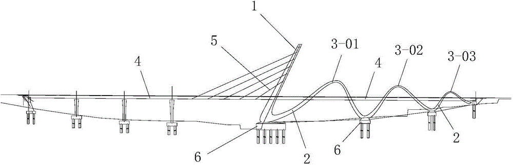
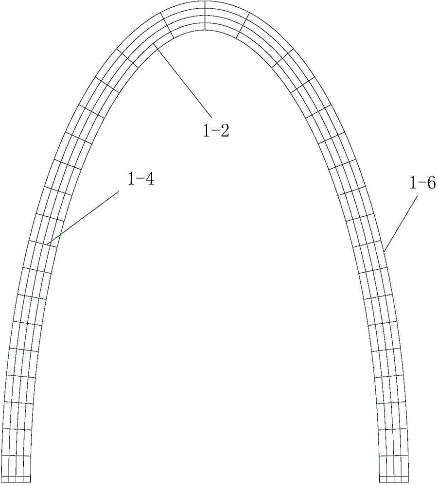
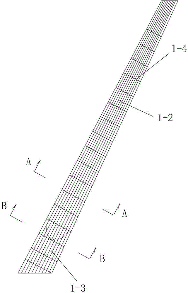
[0085] Such as figure 1 A ribbon-shaped single-tower cable-stayed-rigid frame composite bridge is shown, including the lower support structure of the bridge, the main girder 4 located above the lower support structure of the bridge, which is arranged on the main girder 4 and gradually tilts backward from bottom to top The main tower 1 and two ribbon-shaped support structures located on the rear side of the main tower 1, the main tower 1 is arched, and the structures of the two ribbon-shaped support structures are the same and they are arranged symmetrically on the left and right sides of the main tower 1 On both sides, the two streamer-shaped support structures are fastened together with the main girder 4 and both are arranged along the longitudinal direction of the bridge. Between the main tower 1 and the main girder 4, a plurality of stay cables 5 are arranged, and the stay cables 5 are arranged from top to bottom and are all located at the front side of the main tower 1. Ea...

Embodiment 2

[0138] In this example, if Figure 9 As shown, the number of the single-tower cable-stayed ribbon-shaped combined force-bearing system is two, and the two single-tower cable-stayed ribbon-shaped combined force-bearing systems are arranged symmetrically.

[0139] During actual construction, according to specific needs, the number of the single-tower cable-stayed ribbon-shaped combined stress system is adjusted, and by increasing the single-tower cable-stayed ribbon-shaped combined stress system, the ribbon-shaped independent stress system of the construction is increased. Spanning capacity of tower cable-stayed-rigid frame composite bridge.

[0140] In this embodiment, the structures, connections and construction techniques of the remaining parts are the same as those in Embodiment 1.


PUM


Abstract

The invention discloses a ribbon-shaped single-tower cable-strayed-steel structure combined bridge and a construction process thereof. The combined bridge comprises a lower supporting structure, a main beam, an arch-shaped main tower which is arranged on the main beam and gradually backwards inclined from bottom to top, and two ribbon-shaped supporting structures which are positioned at the rear side of the main tower; the two ribbon-shaped supporting structures are both integrally fixedly connected with the main beam; the two-ribbon-shaped supporting structures and the main beam are lengthways arranged along the bridge direction; a plurality of cable-strayed ropes are arranged between the main tower and the main beam; each ribbon-shaped supporting structure is divided into a lower ribbon-shaped supporting structure and an upper ribbon-shaped connecting structure through the main beam. The construction process of the combined bridge comprises the steps of 1, constructing the lower supporting structure; 2, constructing the lower ribbon-shaped supporting structure; 3, constructing the main beam; 4, constructing the main tower and the upper ribbon-shaped connecting structure. The combined bridge is reasonable in structural design, convenient to construct, outstanding in mechanical performance and a good in use effect; a non-back cable-stayed bridge and a continuous rigid structural bridge are effectively combined, and the advantages of the two bridges are brought into full play.

Description

technical field [0001] The invention belongs to the technical field of bridge construction, and in particular relates to a ribbon-shaped single-tower cable-stayed-rigid structure composite bridge and its construction technology. Background technique [0002] At present, with the development of bridge technology and design theory, various long-span and super-long bridge structures have become more common. Moreover, composite structure bridges have been widely used in bridge engineering due to their multiple advantages such as overall stress and material use, rationality, economy, and better landscape effects. However, from the perspective of overall development trend, the existing bridge design scheme still has the problem that the conventional structure bridge is large but not new, and the composite structure bridge is new but not simple. Not often. The cable-stayed bridge without back cables is a commonly used form of cable-stayed bridges, and its landscape effect and mec...

Claims


Application Information

Patent Timeline
IPC IPC(8): E01D12/00E01D11/04E01D21/00
CPCE01D12/00E01D19/02E01D19/14E01D21/00E01D2101/268
Inventor 龙刚刘永健侯宁邱洁霖孙虎平
Owner XIAN MUNICIPAL ENG DESIGN & RES INST
Why Eureka
Try Eureka