Prepositioned turbogenerator room combined with denitration steel structure and arranged on high position

A technology of steam turbine generator and steam turbine generator set, which can be applied in the directions of machines/engines, mechanical equipment, steam engine devices, etc., and can solve problems such as cost increase

Active Publication Date: 2015-04-29
CHINA POWER ENG CONSULTING GRP CORP EAST CHINA ELECTRIC POWER DESIGN INST
View PDF7 Cites 1 Cited by
  • Summary
  • Abstract
  • Description
  • Claims
  • Application Information

AI Technical Summary

Problems solved by technology

will also lead to a substan

Method used


Image

  • Prepositioned turbogenerator room combined with denitration steel structure and arranged on high position
  • Prepositioned turbogenerator room combined with denitration steel structure and arranged on high position
  • Prepositioned turbogenerator room combined with denitration steel structure and arranged on high position

Examples


Embodiment 1

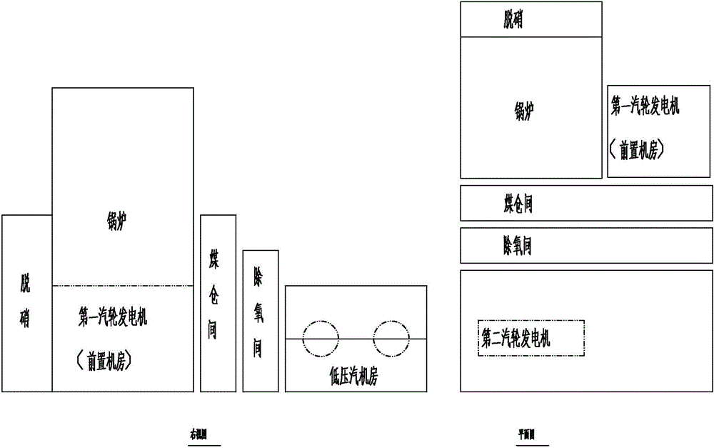
[0078] image 3 It is a structural diagram of the pre-turbine generator room combined with the denitration steel structure in the first embodiment of the present invention.

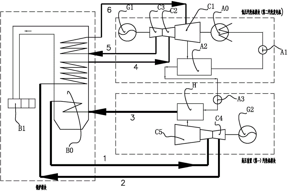
[0079] and figure 2 Compared with the shown low-level turbo-generator main workshop, the present invention transforms the denitrification steel frame into a high-level pre-turbine generator room combined with the denitrification steel structure, and the front-end unit (the high-voltage shaft system of the turbo-generator set Part) is arranged in whole or in part on the upper part of the denitrification steel frame, and the original turbo-generator set is reserved and utilized as the low-temperature and low-pressure part of the turbo-generator shafting, and is still arranged in the low-level turbine room.

[0080] The denitrified steel structure of the present invention is combined with a high-position pre-turbine generator room, including: a boiler, a coal bunker room, a deoxygenation room, a first turb...

Embodiment 2

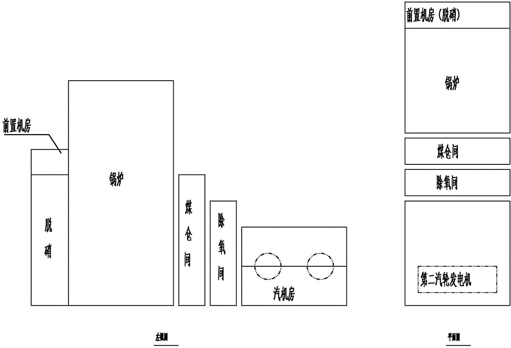
[0087] Figure 4 It is a structural diagram of the pre-turbine generator room with denitrated steel structure combined with high-level arrangement in Example 2 of the present invention.

[0088] Embodiment 2 of the present invention is similar to Embodiment 1, except that the denitrification steel frame is arranged on the side of the boiler.

[0089] The high-positioned pre-turbine generator room in this embodiment 2 can reduce the distance of the main steam pipeline by 50%-70%, and the relative length of the main steam pipeline can reach 2 / 9, and the absolute length is ≤40m. The length of the connecting piping system can be shortened to 40m, the cost of the main steam pipeline can be saved by 50%, the overall cost can be reduced by 20%, and the efficiency of the main steam pipeline can be increased by more than 50%.


PUM

PropertyMeasurementUnit
Lengthaaaaaaaaaa

Abstract

The invention provides a prepositioned turbogenerator room combined with a denitration steel structure and arranged on a high position. The room comprises a boiler, a coal cabin chamber, an oxygen removing chamber, a first turbogenerator, a second turbogenerator and a denitration device, wherein the coal cabin chamber is arranged adjacently on one side of the boiler; the oxygen removing chamber on one side adjacent to the far end of the side coal cabin chamber; a steam turbine room is arranged on one adjacent side of the oxygen removing chamber; the second turbogenerator is arranged in the steam turbine room; the second turbogenerator is provided with a high-pressure cylinder, a middle-pressure cylinder, a low-pressure cylinder, a low-pressure heater and an oxygen remover, a steam condenser, a condensation water pump and a first generator; a composite steel frame is arranged on one side of the near end of the boiler or one side face of the boiler; a prepositioned machine room is arranged on the upper part of the composite steel frame; the first turbogenerator is arranged in the prepositioned machine room. By the aid of the prepositioned turbogenerator room, the occupying area of a prepositioned set is reduced; high-temperature and high-pressure pipelines are saved; the investment of a high-temperature pipe system can be greatly reduced and the normal operation efficiency is improved.

Description

technical field [0001] The invention relates to the field of power plant structures, in particular to a front steam turbine generator room combined with a denitration steel structure and arranged at a high position. Background technique [0002] The double reheat upgrade update technology fully combines the front-end machine technology with the double reheat ultra-supercritical technology, achieving the effect of greatly improving the thermal efficiency of the unit and only slightly increasing the transformation cost. That is to increase the pressure and temperature of the main steam, and the exhaust steam will be reheated to raise the temperature after the front-end unit works. And increase the output of the unit; at the same time, update the main equipment that has been running for a long time, which can prolong the operating life of the whole unit. [0003] In a conventional thermal power plant, due to the large volume and heavy equipment of the turbogenerator, it is usu...

Claims


Application Information

Patent Timeline
IPC IPC(8): E04H5/02F01K13/00
CPCE04H5/02F01K13/00
Inventor 冯琰磊申松林林磊施刚夜邓文祥何文珊
Owner CHINA POWER ENG CONSULTING GRP CORP EAST CHINA ELECTRIC POWER DESIGN INST
Why Eureka
Try Eureka