Distributed-flame combustion chamber head structure

A combustion chamber, distributed technology, applied in combustion chambers, continuous combustion chambers, combustion methods, etc., can solve the problems of uneven heat release, increase cooling consumption, and heat release concentration, achieve a wide range of fuel adaptation, suppress heat Sound oscillations, effects that dampen spawn rate

Active Publication Date: 2015-04-29
CHINA UNITED GAS TURBINE TECH CO LTD
View PDF3 Cites 12 Cited by
  • Summary
  • Abstract
  • Description
  • Claims
  • Application Information

AI Technical Summary

Problems solved by technology

As a result, the heat release of various parts inside the combustion chamber is uneven, so there are the following problems:
[0003] (1) The influence of hot spot changes on the cooling of the flame tube brought about by the uneven heat release process. The cooling design of the combustion chamber needs to consider the cooling arrangement of all hot spots, which increases the cooling consumption and is not conducive to the improvement of the combustion chamber level;
[0004] (2) Uneven heat release leads to local heat release concentration, resulting in thermoacoustic oscillation

Method used


Image

  • Distributed-flame combustion chamber head structure
  • Distributed-flame combustion chamber head structure

Examples


Embodiment 1

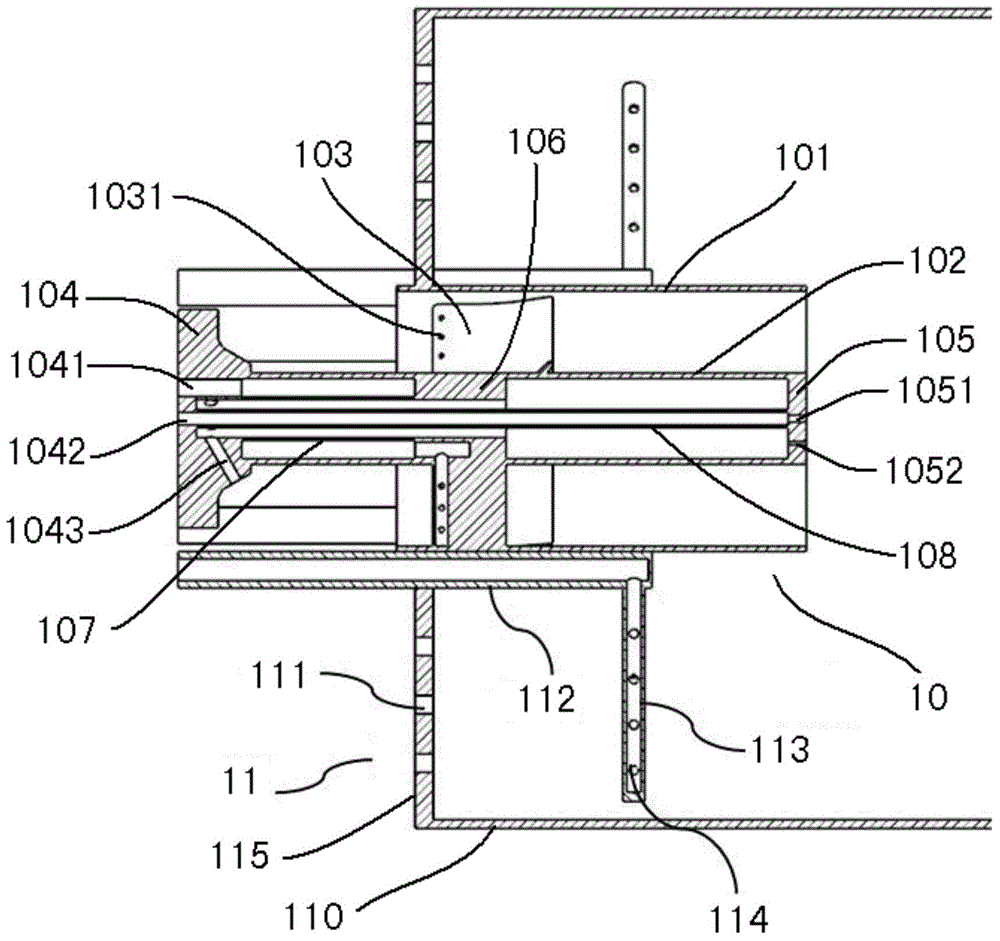
[0025] refer to figure 1 As shown, the combustion chamber head structure of the distributed flame of the present invention includes: a main nozzle 11 , a central duty nozzle 10 , a combustion outer wall 110 and a combustion end plate 115 , and the main nozzle 11 includes a plurality of main fuel pipes 112 . The combustion end plate 115 is fixed on the rear end of the combustion outer wall 110, and the combustion outer wall 110 and the combustion end plate 115 form a cylindrical structure with an open front end. The central duty nozzle 10 is arranged in the center of the combustion end plate 115 . One end of a plurality of main fuel pipes 112 is connected to the fuel gas passage hole on the fuel end plate 115, and the other end passes through the combustion end plate 115, extends into the outer wall of the combustion chamber 110, and is evenly arranged on the center duty nozzle 10. Around the outside, the portion of each main fuel pipe 112 protruding into the outer wall 110 of...

Embodiment 2

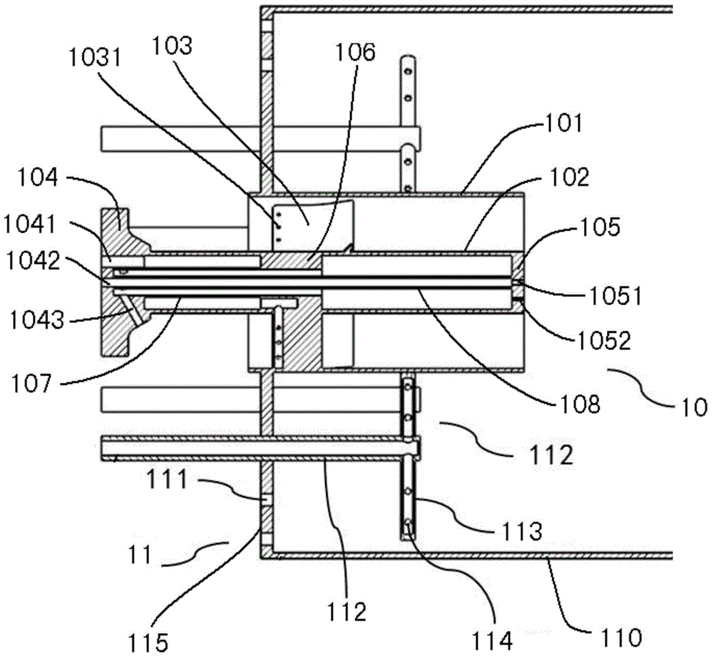
[0034] This embodiment is basically the same as Embodiment 1, the difference is: refer to figure 2 As shown, in this embodiment, there are two radial fuel pipes 113 on each main fuel pipe 112, and the two radial fuel pipes 113 are located on the same radial section. In addition, three or more radial fuel pipes 113 may be used.

[0035] The working process of the present invention is as follows: part of the air fuel enters the central duty nozzle 10 to form a central diffusion flame and a central premixed flame to provide ignition energy for the main nozzle fuel-air mixture, and part of the air enters the outer wall of the combustion chamber 110 at a high speed from the main air inlet 111 , forming a high-speed jet air, part of the fuel enters the main fuel pipe 112 from the end cover, and is ejected from the main fuel injection hole 114 of the radial fuel pipe 113, and is mixed with the high-speed jet air to form a high-speed jet mixture, which is discharged downstream of the...


PUM


Abstract

The invention relates to the technical field of gas turbine combustion chambers, and discloses a distributed-flame combustion chamber head structure. The distributed-flame combustion chamber head structure comprises a main spray nozzle, a central on-duty spray nozzle, a combustion chamber outer wall and a combustion end plate, wherein the main spray nozzle comprises a plurality of main combustion pipes; the combustion end plate is fixed at the back end of the combustion chamber outer wall; the central on-duty spray nozzle is arranged in the center of the combustion end plate; the main combustion pipes pass through the combustion end plate, extend into the combustion chamber outer wall, and are arranged around the outer side of the central on-duty spray nozzle; at least one radial combustion pipe is arranged on a part, which extends into the combustion chamber outer wall, of each main combustion pipe; the radial combustion pipes are positioned on the upstream of the front end of the central on-duty spray nozzle; each radial combustion pipe is provided with a main fuel spray nozzle; the combustion end plate is provided with a plurality of main air inlets. Distributed flame is established, so that defects caused by non-uniform heat release are overcome, and the generation rate of nitrogen oxides is restrained.

Description

technical field [0001] The invention relates to the technical field of gas turbine combustors, in particular to a combustor head structure with distributed flames. Background technique [0002] The combustor is one of the three core components of an industrial gas turbine, which directly determines whether the pollutants of the gas turbine meet the mandatory requirements of environmental protection regulations. Industrial heavy-duty gas turbine combustors have a variety of combustion organization forms, the core of which is to fully combust fuel and air in a proper way under many limiting factors. The limiting factors mentioned here mainly include the pressure drop through the combustion chamber, the metal wall temperature of the combustion chamber, the temperature distribution of the combustion chamber outlet, and the vibration of the combustion chamber. As far as the mainstream combustion chamber in modern industrial heavy-duty gas turbines is concerned, the combustion ba...

Claims


Application Information

Patent Timeline
Patent Type & Authority Applications(China)
IPC IPC(8): F23R3/38
Inventor 李珊珊吕煊方子文张永良陈伟
Owner CHINA UNITED GAS TURBINE TECH CO LTD
Why Eureka
Try Eureka