
Flue gas treatment equipment of range hood

A technology for range hood and flue gas treatment, which is applied in the field of range hoods, and can solve problems such as insufficient filtration of filter screens and circular tubes, failure to consider the recycling of flue gas heat, and oily gas pollution.

Active Publication Date: 2015-04-29
厦门润昕厨具有限公司
View PDF4 Cites 1 Cited by
  • Summary
  • Abstract
  • Description
  • Claims
  • Application Information

AI Technical Summary

Problems solved by technology

Taking the Chinese-style range hood as an example, in the process of exhausting the range hood, an oil-gas separation process will be carried out in the range hood to avoid the oil-containing gas being directly discharged into the atmosphere and causing pollution; the current oil-gas separation equipment is mainly filtered through a filter or interleaved. Stacked circular pipes are used for oil-retaining treatment, and both the filter screen and the circular pipe have insufficient filtration, because the contact surface between the filter screen and the circular pipe and the flue gas is relatively small, and the separation rate of oil and water in the flue gas is insufficient Fifty percent, so there will still be a lot of oily gas directly discharged into the atmosphere, causing pollution, and the current flue gas treatment equipment of range hoods does not take into account the recycling of flue gas heat while separating oil and gas , now the heat generated by the flue gas discharged from the range hood is wasted, and the oil and water separated from the flue gas are basically discharged directly into the sewer, resulting in a waste of resources

Method used


Image

  • Flue gas treatment equipment of range hood
  • Flue gas treatment equipment of range hood

Examples


Embodiment Construction

[0014] In order to have a further understanding and understanding of the structural features of the present invention and the achieved effects, the preferred embodiments and accompanying drawings will be used for a detailed description, as follows:

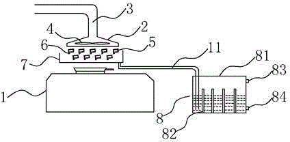
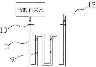
[0015] Such as figure 1 , figure 2 As shown, a flue gas treatment device for a range hood includes a range hood casing 2 arranged above a cooker 1 , a suction channel 3 is arranged inside the range hood casing 2 , and the end of the suction channel 3 A fan 4 is arranged above the stove, and an oil baffle is arranged below the fan 4. The oil baffle is composed of multiple stacked square oil baffles 5, and each layer of square oil baffles 5 is connected from end to end and is circuitous. , the installation positions of the adjacent square oil retaining pipes 5 of each layer are staggered, and the pipe body of the upper square oil retaining pipe is located above the pipe body gap of the adjacent lower floor square oil retaining pip...


PUM


Abstract

The invention relates to flue gas treatment equipment of a range hood. The flue gas treatment equipment comprises a range hood shell arranged above a hearth, wherein an oil baffle plate is arranged below and consists of multiple layers of mutually superposed square oil baffle pipes, the installation positions of each layer of adjacent square oil baffle pipes are mutually staggered, the installation positions of the square oil baffle pipes are gradually inclined downwards from the front end direction of the hearth to the rear end direction of the hearth, the square oil baffle pipes are inclined to either side about own center axes, oil-water collecting tanks extending towards the length directions of the square oil baffle pipes are formed in one sides of the square oil baffle pipes at relatively low positions, the square oil baffle pipes are hollow pipes, one ends of the square oil baffle pipes are communicated with external municipal tap water, and other ends of the square oil baffle pipes are communicated with independent water consumption pipelines in kitchens. Compared with conventional flue gas treatment equipment, the equipment is high in oil-gas separation efficiency and is provided with oil-water separation equipment to achieve the purpose of recycling resources, and during cooling of flue gas, heat released by the flue gas is absorbed by the square oil baffle pipes, so that the heat of the flue gas is recycled.

Description

technical field [0001] The invention relates to a range hood, in particular to a smoke treatment device for the range hood. Background technique [0002] The range hood is a relatively popular kitchen electrical equipment, which is used to exhaust the oily fume generated during the cooking process of the stove. Taking the Chinese-style range hood as an example, in the process of exhausting the range hood, an oil-gas separation process will be carried out in the range hood to avoid the oil-containing gas being directly discharged into the atmosphere and causing pollution; the current oil-gas separation equipment is mainly filtered through a filter or interleaved. Stacked circular pipes are used for oil-retaining treatment, and both the filter screen and the circular pipe have insufficient filtration, because the contact surface between the filter screen and the circular pipe and the flue gas is relatively small, and the separation rate of oil and water in the flue gas is insu...

Claims


Application Information

Patent Timeline
IPC IPC(8): F24C15/20
CPCF24C15/20
Inventor 蔡钟坤
Owner 厦门润昕厨具有限公司
Learn More