
Solar thermal collector and method for converting solar energy into mesothermal heat energy by utilizing same

A technology of solar heat collectors and heat collecting tubes, which is applied in the direction of solar heat collectors, solar thermal energy, and solar heat collectors using working fluids. Problems such as high cost of thermal mode can achieve the effect of improving system reliability, excellent light transmission and reducing system cost

Active Publication Date: 2015-04-29
NANJING CHENGYUAN SOLAR HEATING
View PDF10 Cites 15 Cited by
  • Summary
  • Abstract
  • Description
  • Claims
  • Application Information

AI Technical Summary

Problems solved by technology

[0004] The object of the present invention aims at the deficiencies of the above-mentioned prior art to provide a kind of solar heat collector and the method that utilizes it to convert solar energy into medium-temperature heat energy, this solar heat collector and the method that utilizes it to convert solar energy into medium-temperature heat energy It can realize self-tracking of sunlight, and the invention solves the problems of high cost of general trough, tower, butterfly and Fresnel heat collection modes, which cannot be combined with factory buildings, and the non-tracking focus mode with small focus ratio The problem is that the sunlight focusing ratio of 5 to 20 times can be realized. Through the present invention, solar energy can be efficiently converted into medium-temperature heat energy, and a stable medium-temperature heat source of 100°C to 300°C can be obtained.

Method used


Image

  • Solar thermal collector and method for converting solar energy into mesothermal heat energy by utilizing same
  • Solar thermal collector and method for converting solar energy into mesothermal heat energy by utilizing same

Examples


Embodiment 1

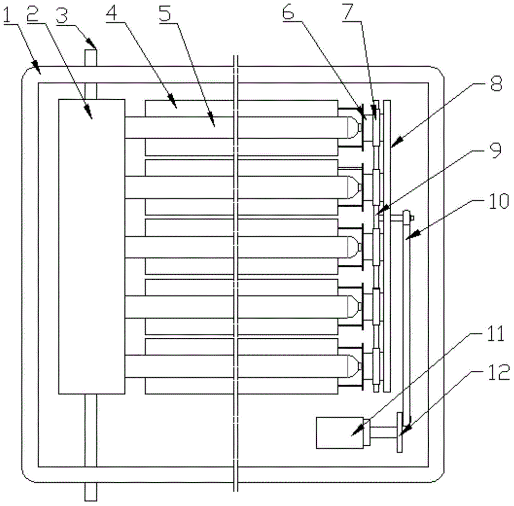
[0031] see figure 1 , the solar heat collector includes a heat collecting tube 5, and also includes a frame 1, a reflector 4 and a reflector rotation control device; the reflector 4 and the reflector rotation control device are located in the frame 1; the reflector 4 is located in the collector The back of the heat pipe 5 and the focal axis of the emission plate 4 coincide with the axis of the heat collection tube 5; the reflection plate 4 is used to gather solar energy to the heat absorber of the heat collection tube 5 by reflection to form thermal energy; the rotation control of the reflection plate The device is used to drive the emitting plate 4 to rotate around the focus axis, so that the emitting plate 4 rotates following the change of the sun's rays. A reflection plate 4 is arranged on the back of each heat collecting tube 5 . see figure 2 , the reflector rotation control device includes a controller, an external sensor, a photoelectric switch and a reflector rotatio...

Embodiment 2

[0036] In Embodiment 2, the reflector rotation control mechanism includes a connecting rod 6, a motor 11, a transmission gear 7, a bracket 8, a rack 9, a transmission rod 10, a motor 11 and a motor turntable 12; one end of the connecting rod 6 is connected to The reflection plate 4 is fixedly connected, and the other end is fixedly connected with the transmission gear 7; the axis of the connecting rod 6 and the axis of the transmission gear 7 coincide with the axis of the heat collecting tube 5; the transmission gear 7 is rotatably mounted on the bracket 8; the motor The rotating disk 12 is fixedly installed on the transmission shaft of the motor 11, and one end of the transmission rod 10 is connected with the motor rotating disk 12, and the other end is connected with the rack 9; the rack 9 is located below the transmission gear 7 and meshes with the transmission gear 7; The motor 11 drives the transmission rod 10 to reciprocate along the axis of the transmission rod 10 throug...

Embodiment 3

[0038] In Embodiment 2, the reflector rotation control mechanism includes a connecting rod, a transmission gear, a bracket, a rack, a motor, and a motor gear; one end of the connecting rod is fixedly connected to the reflector, and the other end is fixedly connected to the transmission gear; The axis of the rod and the axis of the transmission gear coincide with the axis of the heat collecting tube; the transmission gear is rotatably mounted on the bracket; the motor gear is fixedly mounted on the transmission shaft of the motor, and the motor gear meshes with the rack; The rack is located below the transmission gear and meshes with the transmission gear; the motor drives the rack to reciprocate along the length direction of the rack through the motor gear, the rack drives the transmission gear to rotate, and the transmission gear drives the reflector to rotate; the The photoelectric switch is installed on the transmission gear, and the controller detects the initial position o...


PUM

PropertyMeasurementUnit
Opening widthaaaaaaaaaa
Thicknessaaaaaaaaaa
Thicknessaaaaaaaaaa

Abstract

The invention discloses a solar thermal collector which comprises a thermal collection pipe, a framework, a reflecting plate and a reflecting plate rotation control device; the reflecting plate is positioned on the back side of the thermal collection pipe, and a focal axis of the reflecting plate is coincident with the axis of the thermal collection pipe; the reflecting plate is used for gathering the solar energy onto a thermal absorbing body of the thermal collection pipe; the reflecting plate rotation control device is used for driving the reflecting plate to rotate by taking the focal axis as a center, so that the reflecting plate can rotate along the change of sunshine. The invention further discloses a method for converting solar energy into mesothermal heat energy by utilizing the solar thermal collector, so that the self tracking of sunshine can be realized, the problems of common tank type, tower type, butterfly type, Fresnel type thermal collection modes are high in cost, and incapable of combining with a factory building and the problem that the non-tracking focusing mode is small in focusing ratio can be solved, 4-20 times of solar focusing ratio can be realized, solar energy is efficiently converted into mesthermal heat energy to obtain a stable mesothermal heat source of 100DEG C-300DEG C.

Description

technical field [0001] The invention relates to a flat-plate focusing type medium-temperature solar heat collector and a method for preparing a medium-temperature heat source, in particular to a solar heat collector and a method for converting solar energy into medium-temperature heat energy by utilizing the same. Background technique [0002] Medium-temperature solar thermal utilization technology is the main development trend of solar thermal utilization technology in the future. Its main work is mainly between 100°C and 300°C. It can be widely used in many industries such as food, chemical industry, drying, power generation, clothing, printing and dyeing, etc., and has broad market prospects. At present, solar thermal utilization technology mainly focuses on low-temperature heat utilization (below 80°C) and high-temperature power generation applications (above 400°C). Low-temperature solar heat utilization technology, because its working temperature is below 80°C, the e...

Claims


Application Information

Patent Timeline
IPC IPC(8): F24J2/24F24J2/10F24J2/05F24J2/40F24J2/46F24S10/40F24S10/70F24S23/70
CPCY02E10/44
Inventor 朱雷
Owner NANJING CHENGYUAN SOLAR HEATING
Learn More