
Distributed microstructure sensor network based on time division wavelength division multiplexing and its application method

A technology of time division wavelength division multiplexing and sensor network, which is applied in the direction of time division optical multiplexing system and the use of optical devices to transmit sensing components, etc., which can solve the problem that the system performance has not been greatly improved, and the lack of wavelength division frequency division multiplexing mining , the limited number of multiplexed gratings, etc., to reduce operating and management costs, improve reusability and spatial recognizability, and increase the demodulation rate

Active Publication Date: 2017-06-30
HUAZHONG UNIV OF SCI & TECH
View PDF4 Cites 0 Cited by
  • Summary
  • Abstract
  • Description
  • Claims
  • Application Information

AI Technical Summary

Problems solved by technology

Cathy Crunelle from Mons College in Belgium implemented a λ-OTDR system on the basis of wavelength-tuned OTDR technology, using a low-reflectivity grating (R<10%) junction and wavelength division multiplexing (WDM), but the number of multiplexed gratings is limited
The application number is 201210390000.8, and the patent application titled "ultra-large-capacity time-division wavelength-division fiber grating sensing system and its query method" proposes an ultra-large-capacity time-division multiplexing system, which realizes large-capacity The addressing and query of optical fiber sensors realizes the time-division multiplexing of large-capacity FBG (Fiber Bragg Grating) units, which has good application value. However, due to the lack of multiplexing of wavelength division and frequency division, the system performance has not been maximized. promote
The application number is 201110414568.4, and the patent application titled "A Large-Capacity Parallel Fiber Bragg Grating Sensor Analyzer" uses space division and wavelength division multiplexing technology, and adopts a synchronous control mechanism to detect and collect multiple optical signals. Realized the multiplexing of sensing units with larger capacity, but this solution uses more photodetectors, which greatly increases the system cost

Method used


Image

  • Distributed microstructure sensor network based on time division wavelength division multiplexing and its application method
  • Distributed microstructure sensor network based on time division wavelength division multiplexing and its application method
  • Distributed microstructure sensor network based on time division wavelength division multiplexing and its application method

Examples


Embodiment Construction

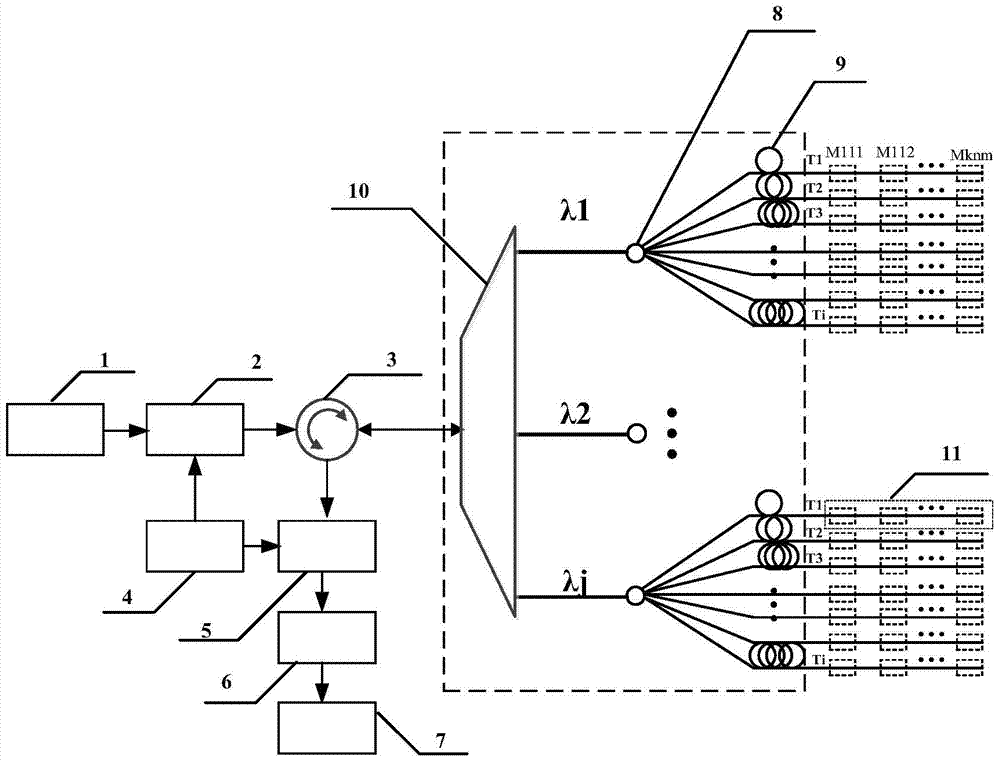
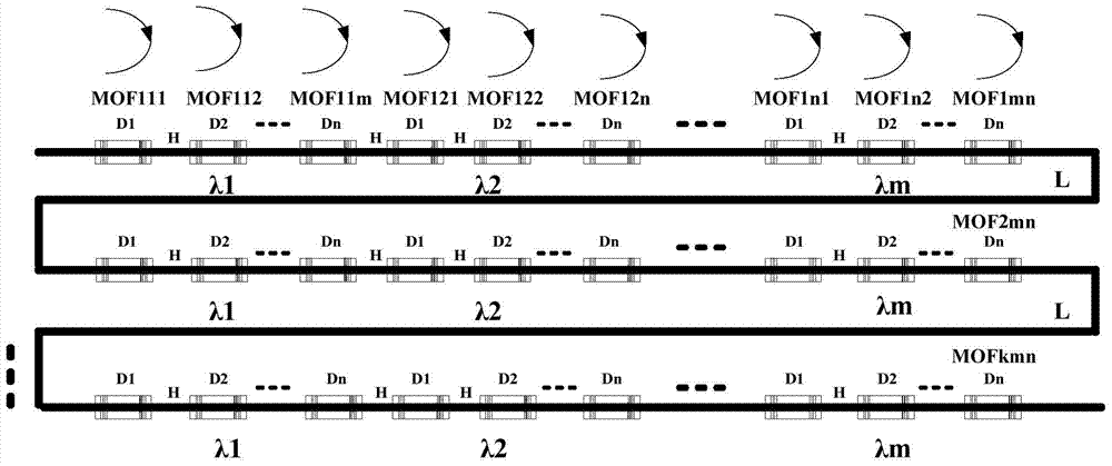
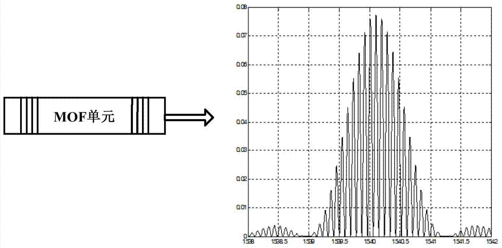
[0031] Aiming at the capacity limitation of the existing distributed optical fiber sensing multiplexing technology, the present invention proposes a distributed microstructure sensing network and its demodulation system based on hybrid wavelength division and time division multiplexing, and adopts a wavelength division / time division multiplexing network sensing architecture , and design a distributed microstructure optical fiber sensing link with three-dimensional encoding characteristics to achieve ultra-large capacity sensing multiplexing. This architecture can multiplex the sensing microstructure array on a large scale without adding demodulation devices, and proposes a microstructured optical time domain reflectometry (MOTDR ) technology, which greatly improves the sensitivity and spatial resolution of the sensing unit, and finally gives the massive information parallel fast processing technology of the sensor network

[0032] A distributed microstructure sensor network ba...


PUM


Abstract

The invention provides a distributed microstructure sensing network based on wavelength division time division multiplexing and its application method. The network includes a broadband light source (1), an optical circulator (3), an optical distribution network and a plurality of distributed An optical fiber sensing link (11), the sensing unit is connected to the demodulation unit through an optical distribution network, an optical circulator (3), and a full-spectrum scanning module (5) in sequence. The invention adopts the hybrid time division / wavelength division network architecture, has the characteristics of super large capacity, super long distance, low unit demodulation cost, high sensing sensitivity, low power consumption, etc., and is suitable for large-scale distributed sensing multiplexing.

Description

technical field [0001] The invention relates to the technical field of optical fiber sensing, realizes a super-large-capacity distributed optical fiber sensing network through the design of a hybrid wavelength division and time division multiplexing system, and proposes a fast demodulation method for the sensing network. Background technique [0002] Optical fiber sensors are mainly used for sensing temperature, stress, pressure and other environmental parameters. Due to their passive and high-precision characteristics, they have been widely used in bridges, dams, oil fields, aerospace, marine monitoring, geological monitoring and other fields, especially based on The distributed optical fiber sensing technology based on the principle of OTDR (Optical Time Domain Reflectometry), with its advantages of distributed measurement, no blind area, high monitoring density, wide monitoring range, and simple sensor structure, greatly meets the application requirements. The distribution...

Claims


Application Information

Patent Timeline
Patent Type & Authority Patents(China)
IPC IPC(8): G01D5/353H04J14/08
Inventor 孙琪真程建伟李晓磊刘德明艾凡
Owner HUAZHONG UNIV OF SCI & TECH
Learn More